This thread has been locked.

If you have a related question, please click the "Ask a related question" button in the top right corner. The newly created question will be automatically linked to this question.

MC34063A: What should be considered when changing the switching frequency by Timing Cap?

Part Number: MC34063A

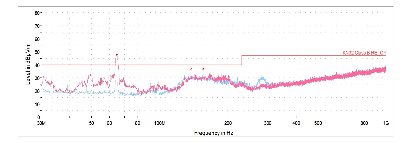
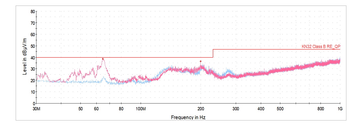
There was a lot of noise in the EMC radiation test.

So, when I changed the timing cap of MC34063A, there was an effect of spreading the spectrum of noise.

Are there any considerations when changing the timing cap to 0.5 pF?

Best regards, 

Jaeseung

  • Hi Jaeseung,

    Thank you for posting.  Using 0.5pF for the timing capacitor sounds too small.  The datasheet recommended switching frequency is up to 100kHz.  The typical characteristics on Page 7 of the datasheet shows CT down to 10pF. 

    EMC radiation may also be contributed to large switching node on your PCB.  You may check that and see if you can reduce it or shield it. 

    Thanks,

    Youhao Xi, Applications Engineering

  • The main cause is that switching noise is radiated through the AC adapter cable because the AC adapter jack and MC34063A are too close together on the PCB.

    So, I put a ferrite core on the AC adapter and it reduced a lot, but it still exceeded the standard value, so an additional consideration was to change the switching frequency.
    When I tried changing the timing capacitor, it seems that it should be set to less than 33pF.

    As you said, it should have a value of 10pF or more, so it will be between 10 and 33pF.

    1) timing capacitor = 1200pF

    2) timing capacitor = 33 pF

    2) timing capacitor = 0.5 pF