This thread has been locked.

If you have a related question, please click the "Ask a related question" button in the top right corner. The newly created question will be automatically linked to this question.

LP8864S-Q1: LED Dimming Freaquency

Part Number: LP8864S-Q1

Hi TI-team

I have the LED Dimming Freaquency set at 152Hz.

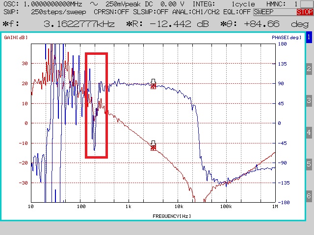
Does this frequency affect the Phase Margin waveform?

The waveform of both Gain and Phase fluctuated around 100Hz to 300Hz.

I think the cause of this vertical shaking is the LED Dimming Freaquency.

Also, does the internal circuit operate at 152Hz even when it is 100% duty ?


Best Regards,

Koji Hayashi

  • Hi Koji,

    If you set the PWM duty cycle to 100%, the PWM duty cycle will not have an effect to phase margin.

  • Hi Charles-san

    Thank you for quick response.

    I got FRA waves with Duty 100%.

    Isn't the reason for the fluctuation of the waveform in the red frame part not the LED Dimming Freaquency ?

    What could be the cause if it is not LED Dimming Freaquency ?

    If you need a schematic, I'll send it, but I can't upload it here.

    Please send me an email or let me know by registering as a friend.


    Best Regards,

    Koji Hayashi

  • Hi Koji,

    You need to set low bandwidth of FRA (for example, 10Hz) for the noise immunity in the low frequency band since the reaction signal is small and also need to increase the amplitude of injection signal at low frequency. Average the results will also be very helpful.

  • Hi Charles-san

    Thank you for quick response.

    Could you please tell me the specific setting method ?

    What does it mean to set the band to 10Hz ?

    Does "need to increase the amplitude of injection signal at low frequency" mean to increase Vpeak 250mV ?

    The understanding of the average is to increase the number of cycles.


    Best Regards,

    Koji Hayashi

  • Hi Koji,

    I am not sure the specific equipment you are using in the experiments. I use the AP300 to test the loop. Typically, we have band-pass filter inside the AP300 to extract the specific frequency component accurately. We have A and B probe to inject the small signal and test the reaction at the output. Just use the filter inside your test equipment to get rid of the harmonics and noise in the system. The amplitude of injection signal is recommended to be 5% of the operation point.

  • Hi Koji,

    Any good news?