This thread has been locked.
If you have a related question, please click the "Ask a related question" button in the top right corner. The newly created question will be automatically linked to this question.
Hi
My customer designed the schematic with BQ24630, found the output voltage unstable and can't charge.
Attached the schematic for your reference.
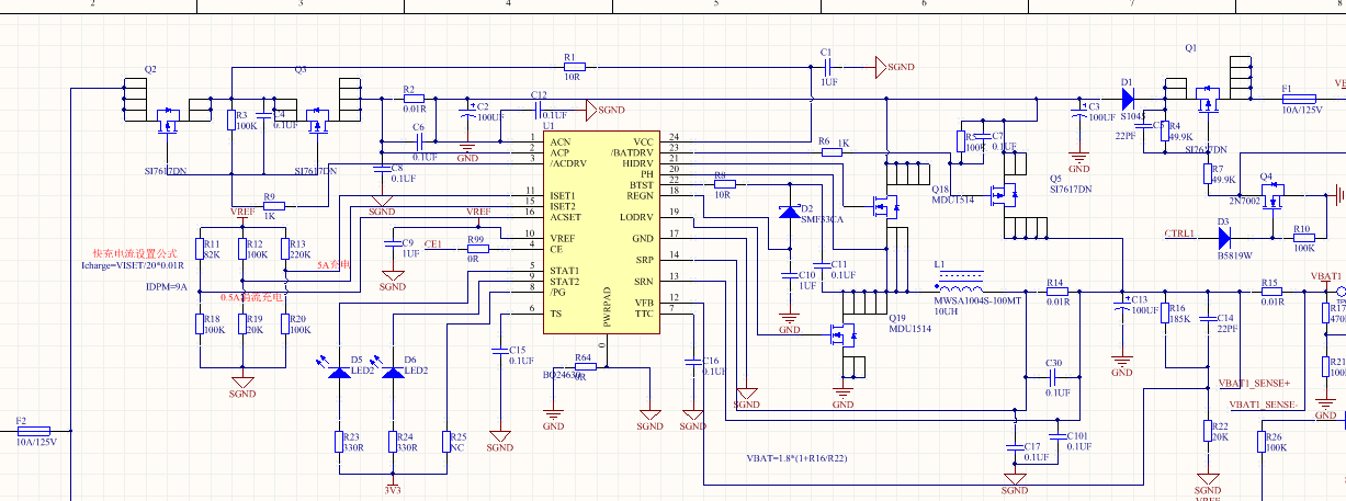
When the adapter is powered on, the voltage at VBAT has been jumping, and the voltage at the VFB terminal I measured is also jumping.
The VBAT is connected to the battery, but can not charge.
The adapter uses DC24V, and set the battery voltage is about 18v.
According to the actual measurement, the PH output is 10v~18v.
Please give some suggestions.
Thanks
Star
Hi Star,
It is better to include the waveforms when you see unexpected behavior. There is no resistor network on TS in the schematic. TS needs to be held at a DC voltage in the normal operating range if no thermistor is used. I would recommend replacing C2 with 2x10uF capacitors and a 0.1uF with another pad for a 0.01uF ceramic capacitor at the drain of the HSFET.
Hi Kedar Manishankar
Thanks for your reply.
After adding a normal voltage on TS pin the battery can charge normal. But the charging current is only 0.6A. The schematic is design for 5A.
When the battery is full discharged the charging current still can not reach 5A.
How to increase the charging current.
Thanks
Star
Hi Star,
Are you measuring the real battery voltage? Most likely the charger is already in CV mode, so output voltage is being regulated while charge current has been allowed to taper down. Log the VFB voltage instead.
How low are you discharging the battery?
Hi Kedar Manishankar
Thanks for your reply.
When discharge the battery to empty then charge, the charging current still very small.
Thanks
Star