This thread has been locked.

If you have a related question, please click the "Ask a related question" button in the top right corner. The newly created question will be automatically linked to this question.

BQ24040: PG signal behaviour doesn't match datasheet

Part Number: BQ24040

Dear TI, 

We've got the following issue:

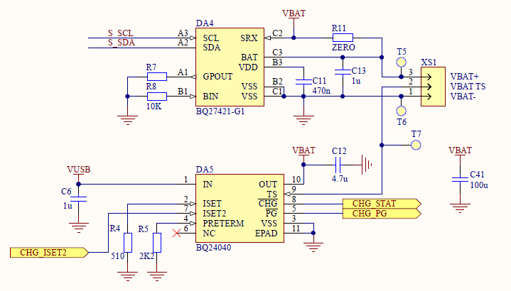
1. On charging phase both CHG and PG pins go low, as expected.

2. On fully charged battery and IN = 5V we have CHG = hi-Z (as expected) and PG = hi-Z. 

For p.2, what's going wrong? Should we expect PG still have active (low) level when charging cable is connected and battery is fully charged?

  • Hi Dmitry,

    Do you have a schematic I can look at to ensure everything is set up correctly? Can you show a waveform with measurements for the IN, BAT, and /PG where you observed p.2?

  • Hi Anthony, 

    it's here. R11 is NC. CHG and PG pins are directly connected to the MCU inputs with internal pull-ups.

    Unfortunately, it's hard to get a waveform right now. Do you have any ideas to investigate the issue further? 

  • Hi Dmitry,

    We'll see what we can do with the information. Are you able to replicate this behavior if you don't use internall pull ups (if this is possible)? I also noticed that your  ISET resistor is 510-Ohms. We recommend putting it between 540-Ohm and 10.8-kOhm. Is it possible to increase this resistor value? 

    What are the voltages when you see the issue for the following:

    • TS
    • OUT
    • BAT
    • IN (I know you said 5V in your initial post but would you be able to measure again when you measure the above?)

  • Hi Anthony, 

    Thanks, we'll check different resistor values later. Should note that we have the same behaviour independently on ISET2 level for 100, 500 and resistor-based settings; still, the setting works fine - it changes chaging current as it should be.

    Here some diagnostic info from gauge IC for reference:

    internal temp.: 27.7C
    temp.: 27.7C
    voltage: 4118 mV
    nominal available capacity: 984 mAh
    Full Available Capacity: 1041 mAh
    Full Remaining Capacity: 1046 mAh
    Remaining Capacity Filtered: 1046 mAh
    Remaining Capacity Unfiltered: 971 mAh
    Full Charge Capacity: 1121 mAh
    Full Charge Capacity Flitered: 1121 mAh
    Full Charge Capacity Unfiltered: 1028 mAh
    Average Current: -50 mA
    Standby Current: -3 mA
    Max Load Current: -226 mA
    Average Power: -206 mW
    State Of Charge: 94 %
    State Of Charge Unfiltered: 95 %
    State Of Health: 91 %, status 1

    Voltages are:

    IN = 5.005V

    VBAT+ = 4.115V (could differ a bit from gauge report due to uncertainities and changing of current drawn by system)

    TS = 0.522V

    difference between OUT and system power (gauge input to output voltage): around 0.5 - 0.7 mV with steady state current drawn by whole schematic

  • Hey Dmitry,

    Thanks for the information. It looks like charging is working properly. Is this issue seen on multiple units and is the observation reoccurring consistently? It sounds like you've already got this on a PCB is this correct? 

  • Hi Anthony, 

    I'm sorry for that, we've found that there is a firmware bug on current samples.

    There was an issue with first batch of device samples, but it was related to poor soldering of PG and STAT pins. For now, all works fine.

    Anyway, thank you for help.