This thread has been locked.

If you have a related question, please click the "Ask a related question" button in the top right corner. The newly created question will be automatically linked to this question.

BQ25505: solar charging and USB charging together

Part Number: BQ25505
Other Parts Discussed in Thread: BQ24210, BQ24045

Hi Team,

My customer now consider to use BQ25505 to design, here are two questions.

  • In addition to the boost function, does BQ25505 include charge management? Do customer need to use another charging IC?
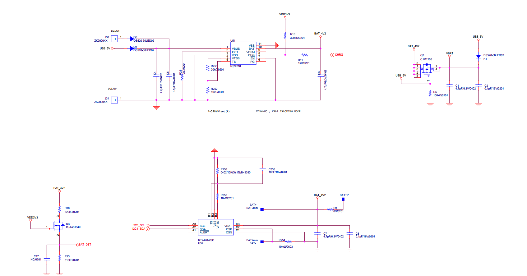
  • Does it support the use of adapters and solar charging together? Actually customer‘s application is outdoor wearable watch. In their normal wearable watch, they use USB adapter to charge the cell. However, in their new application, they want to develop outdoor wearable watch, which is compatible with solar charging. Customer want to know whether their solar charging can be realized by adding this chip to the original USB charging. Customer want to have solar charging and USB charging together.

  • Hi Amelie,

    By charge management, do you mean power path with supplement mode?  If so, then no.  The VBAT_SEC pin is connected to VSTOR through a single PFET that is used only to provide battery undervoltage protection.

    The charger is a boost charger only so its input MPP voltage must be below the final battery voltage.  If the adapter is 5V and the battery voltage is 4.2V, the boost charger can not regulate current.  In this case, the customer must use a second battery charger for the adapter with that charger's output connected in parallel to the BQ25505 VBAT_SEC pin.

    Regards,

    Jeff

  • Thanks Jeff.

    Do you have recommendation for solar batty charger? The charge current is only 200mA.

  • Amelie,

    If their solar panel output is > 4.2V, then I recommend BQ24210.  It can handle both highZ solar panel and USB input.

    Regards,

    Jeff

  • Hi Jeff,

    Customer consider to use BQ24210

    When not charging, what is the battery leakage current caused by the charging chip? Which of the following parameters reflect this parameter?

  • Hi Amelie,

    IOUT(STDBY)=5uA.  If that is problem, then recommend that they add a PFET from BAT pin to Battery that disconnects the battery when no input source is available.  /PG can drive the gate of the PFET.

    Regards,

    Jeff

  • Thanks Jeff.

    The charge voltage of BQ24210 is 4.2V and do we have p2p to support 4.35V? Customer's battery is 4.35V.

    And the attached file is SCH of customer. Could you also double confirm whether it is ok?

  • Hi Amelie,

    There is no 4.35V version of this device.

    Regarding the schematic, all looks okay except for the pullup resistor from VTSB to TS.

    I am going to forward this post to the key support person for this device.

    Regards,

    Jeff 

  • Hi Amelie,

    I took a quick look at the schematic and it looks like the resistor R253 should be the closest resistor value to 43.764k based on the following equation:

    With V_V45C being 18.6% of VTSB and using a 10k resistor at the TS pin, this becomes (1/(.186))*10k - 10k = 43.763k

    As for the 4.35V p2p, we do not have one that's p2p but we do have some devices in our portfolio such as the BQ24045 that can do 4.35. I do not believe there'd be many changes from what is already there.