This thread has been locked.

If you have a related question, please click the "Ask a related question" button in the top right corner. The newly created question will be automatically linked to this question.

BQ24616: Queries on the behaviour of the charging IC

Part Number: BQ24616

Hi Team,

I have the following queries with the charging IC BQ24616 .Although i have read the datasheet ,I have the below queries to be clarified to proceed with the design.

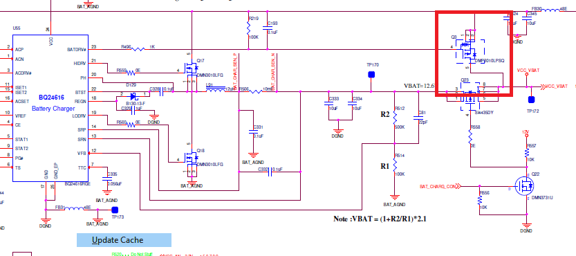
Attached the design schematics FYR.

Note:The VBAT voltage is designed for 12.6V and not 8.4V

Battery_Design.pdf

1.The Voltage on the VFB pin is 2.05V .I have verified the TS pin and it is set to 70% and is between 0 to 45degC .The voltage on the TS pin is >2.4V.So the VFB should be 2.1V as per spec but the voltage is 2.05V on  VFB and hence the Vbat charging voltage is switching between 12.6V and 12.3 but the designed voltage is 12.6V charging. Please let us know why it is switching and not constant 12.6V?
2.We have designed the ISET2 to 0.6A.So the termination current would be 0.6A and the battery stops/terminates charging when the current goes below 0.6A.Please confirm on this understanding ?
3.Kindly let us know how the battery recharge cycle works? As per the datasheet ,recharge starts when the battery voltage has dropped below the recharge threshold (VRECHG).where do i measure the VRECHG voltage i.e at which pin the voltage should fall below 50mV(mentioned w.r.t VREG in spec).I could not understand the recharge threshold from the datasheet. As per my requirement, the charging voltage is 12.6V.At what battery voltage threshold below 12.6V ,the recharge cycle starts? Kindly let me know the definite threshold value dropping from the 12.6V.
4.We have tried charging the battery in constant current mode(1A ISET1 pin updated) but the battery is switching between 1A and 0.6*A) Why is it not charging constantly at 1A and switching between the mentioned current values.Is it the expected behavior?
5.Is there any way to read the voltage of the battery during charging time. We could read the charging voltage of the battery but require to read the battery voltage during charging. Kindly suggest any way to read the battery voltage while charging.

6.Also kindly elaborate the working on how the IC is reading the battery voltage. I ve checked the section 8.3.5 in datasheet but it was not mentioned .

Please clarify on the above queries which would be very helpful in better understanding of the design.

  • Hi Vishal,

       Recharge threshold is detected on VFB pin (50mV is in relation to the 2.1V max regulation voltage - 50mV). TS should be between 68.6% and 53.7% for normal charging.

    With regards to the battery voltage jumping near the max charge regulation voltage, can you take a scope capture of VFB (offset by 2V with 50mV resolution), charge current, PH and STAT.

    With 0.6A termination current, when VFB reaches max charge regulation voltage it will enter CH loop, where output voltage is regulated, and charge current tapers down. When charge current tapers down to the termination set point, and while VFB = 2.1V then termination is detected.

    I will need to see a waveform of the charge current switching between 1A and 0.6A to understand better. Do you have a system load?

    Battery voltage is sensed on VFB of the charger IC. As this is a standalone charger, there is no internal ADC from which to pull out the battery vottage.

  • Hi Kedar,

    Thank you for your reply. Can you please let us know if we can toggle the CE pin every 30 sec? i.e The CE pin will be high for 29sec and low for 1sec.This will disable the IC for 1 sec in every 30secs cycle. Kindly confirm the behavior of the IC with this functionality.

    Also we have tried to disconnect VREF 3.3V tied to CE pin and sourced CE pin with external 3.3V power supply.During this operation the battery Voltage VBAT is not regulating properly and is measuring only 0.8V.The VREF during this is increasing beyond the max 3.3V to >4V .Can we source external supply to the CE pin? Or is mandatory to source CE from VREF ? What is the reason for the VREF to go beyond the max 3.3V rated voltage?Kindly assist on this

  • Hi Kedar,

    Can you please update on this?

  • Hi Vishal,

        There is no issue with toggling the CE pin but what is the purpose for this? What is the reason to pulse charge for 29s every 30s? CE is active high for charge enable.

    VREF is accurately regulated according to EC table specifications. The VREF voltage you are measuring is outside of the absolute maximum ratings. I would double check value of VREF and replace IC if you still observe this, as IC could have been damaged. The CE high threshold is 2.1V and doesn't matter if you use VREF or an external source. In fact the EVM even gives you this capability.

  • Hi Kedar,

    Thank you for the confirmation. We are toggling the CE pin to read the battery voltage during charging condition.

    Can you please let us know how the below function(section 8.3.8)  works?

    "The BATDRV controls a P-channel power MOSFET placed between BAT and the system. When the adapter is not detected, ACDRV is pulled to VCC to keep ACFET off, disconnecting the adapter from the system. BATDRV stays at ACN-6 V to connect the battery to the system"

    When the adaptor is disconnected, how the BATDRV stays at ACN-6V and turns on the BATFET? Will the IC still works when the supply (adaptor) is disconnected? Kindly explain the switchover function of the IC?

  • Hi Vishal,

       The 6V is from the REGN LDO, and this is still powered when adapter is not connected. There is a path from the battery voltage through the body diode of the FET driven by HIDRV, to VCC pin of charger IC. Since VCC = VBAT - body diode drop, the charger will be in SLEEP mode so converter will not be switching. There is break before make logic before turning on BATDRV, and this allows you to connect BAT to supply SYS when no adapter is connected, while also minimizing power dissipation, as power loss will be across RDSON of PFET driven by BATDRV

    As both input reverse blocking FET and BATFET are PFETs, they are driven by -VGS.

  • Hi Kedar,

    Thank you for the explanation. It is very useful. Appreciate your support.

  • Hi Vishal,

       Glad to be of help. I will close this thread now.

  • Hi Kedar,

    Can you please check the attached circuit connection highlighted and confirm if it works fine . I have connected the BATFET drain after the switch(Q23 below batfet) that controls the charging line that is used to turn on or cut off the charging line to the battery(to isolate the battery when required) Kindly let us know your suggestions on this!

  • Hi Vishal,

       This is correct connection of the BATFET. The intrinsic body diode is oriented in the correct direction. You can refer to the EVM schematic available in ti.com as well