


Hello again,
i have been working on other projects the last month. But now I'm back on my h-bridge project.
I have to develope a fullbridge with it's power supply to support a signal with 1kHz, 1.5kV and 60µA. I posted a thread here in the forum in July and got some answers, i understand the most of the points. But i still have some quenstions. The image below shows my simplified solution for the schematic. (sry for the bad resolution)
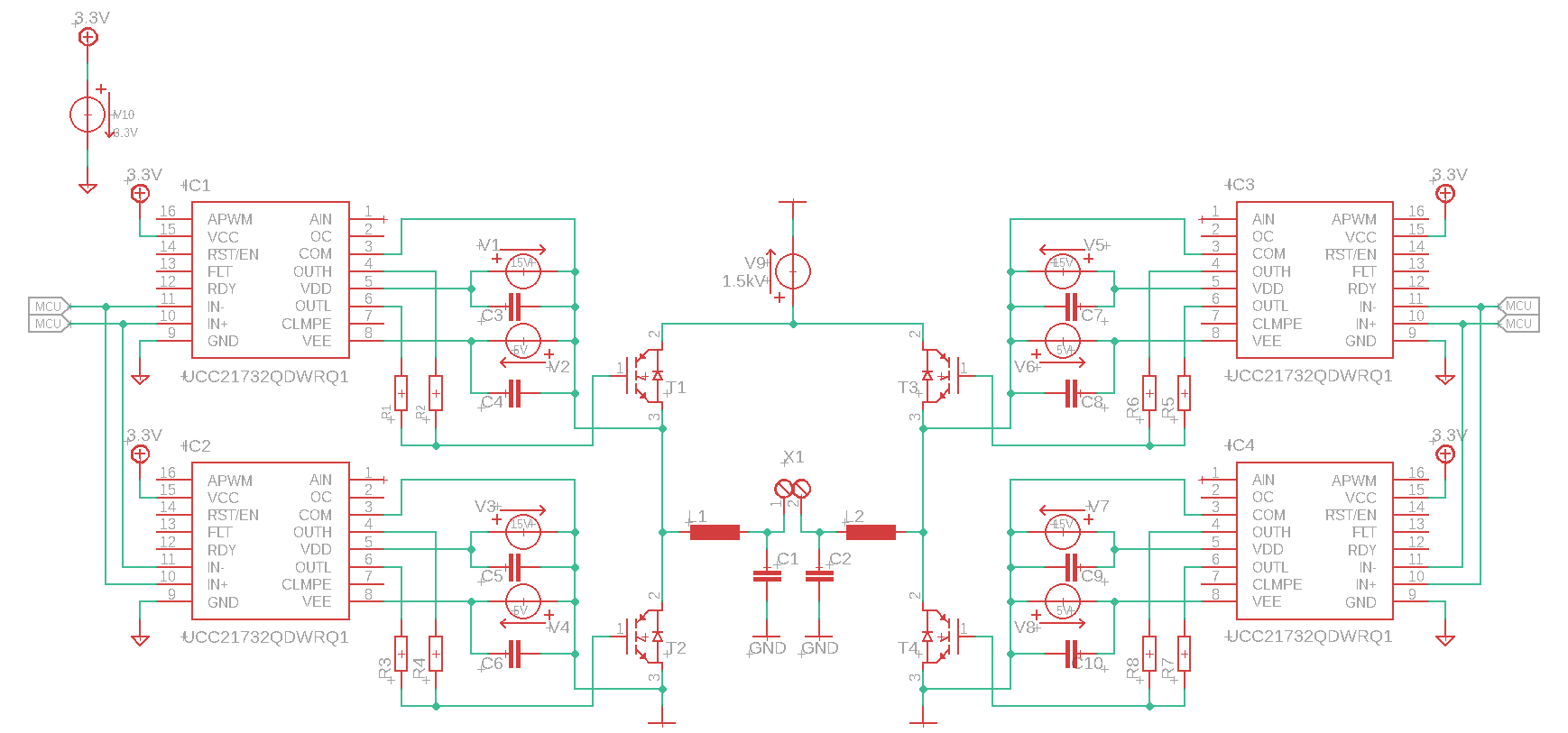
I was told to supply the gate driver with its own power supply which got a common ground. So i built a powersupply for each gate driver with two dcdc-converters in row, V1 and V2 for the driver IC1. Could this solution work? Or did i misunderstood the proposition, that i need a common ground? If it's so i think i need two 1.5kV power supplys which both have a center tap to connect these to inductor on each side. Or is this idea wrong? And on the second side i've got told that I'm not allowed to connect the IGBT like this to the powersupply otherwise i will produce a firework. So what do I've to do? I have no clue
