This thread has been locked.

If you have a related question, please click the "Ask a related question" button in the top right corner. The newly created question will be automatically linked to this question.

LM317: Themal Metrics - Tja

Part Number: LM317
Other Parts Discussed in Thread: , LM1084

[1]
For the LM317 (TO-263 3pin) device, Rθja is listed as 38℃/W. Was this parameter taken based on a 1s or 2s2p test board?

[2]
For the LM317A (SOT-223 4pin) device, Rθja is listed as 59.6℃/W. Was this parameter taken based on a 1s or 2s2p test board?

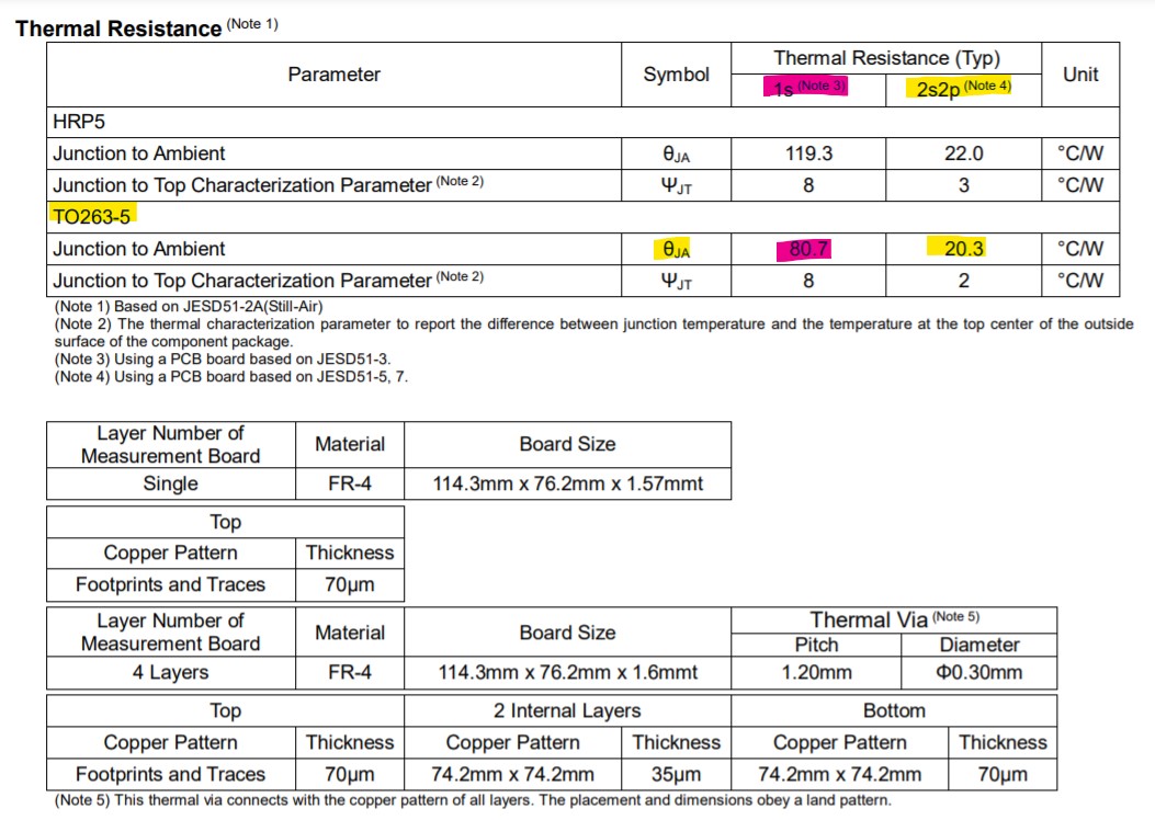
I am looking at promoting the LM317 to replace another device, but that device lists, for a similar TO-263 5pin package, an Rθja of 20.3℃/W...
There is another package similar to the SOT-223, but it lists Rθja as 22℃/W...this seems like a large gap and I just want confirmation.

From the datasheet of the device I want to replace:


  • Hi Darren, 

    JEDEC high-k (2s2p) and low-k (1s0p) are defined in JESD 51-7 and JESD 51-3, respectively. As specified in the Thermal Information table in the datasheet of each device as RθJA. θJA, the datasheet number is derived using a thermal model of the JEDEC High-K Thermal Test Board and is the most popular metric used by designers to evaluate thermal performance.

    The picture you attached does show a better number. Because they are not exactly the same package, the thermal performance could vary. The SOT-223 Rja number seems to be reasonable. You may use google search to check the Rja number on the SOT-223 package, and they are in a similar range but much higher than the 22℃/W number you are comparing to. 

    Here is a thermal note you may find helpful. https://www.ti.com/lit/an/slvae85/slvae85.pdf 


    Regards, 
    Jason Song

  • Hi Jason, 

    I appreciate you helping me out here.
    Just a follow up...because their θja and our θja for a similar package type (TO263-5) are very different.
    They list 20.3℃/W for TO-263, while we list 40.4℃/W (LM1084 TO-263)

    I was reading through the JESD51-7 specification, and the JESD51-3 specification, and JESD51-5 specification:

    From JESD51-5:
    The thermal via must provide thermal contact to the top buried plane in the multi-layer test board only.

    For the competitor's characterization, they state:
    (Note 5) This thermal via connects with the copper pattern of all layers. The placement and dimensions obey a land pattern.

    This varies from the JESD51-5 specification, and allows for better thermal dissipation, as they are transferring heat to two planes instead of a single plane.

    I assume the thermal vias in our testing only attach to a single GND plane (top internal layer) - is this assumption correct?
    If so, would you agree that these Rθja values are not an apples-to-apples comparison, and there is a possibility the values will be closer given a more exact setup?

    Regards,

    Darren

  • Hi Darren, 

    I believe our number strictly follows the JEDEC standards, if there is a note in the customer's datasheet, that note could make their tests slightly different than the JEDEC standard. Having vias connecting through all layers should improve thermal, but it's hard to quantify as they probably use different simulation models for their numbers too. 

    Regards,
    Jason Song