This thread has been locked.

If you have a related question, please click the "Ask a related question" button in the top right corner. The newly created question will be automatically linked to this question.

TPS2363: 12V main 3.3V Main are tripping

Part Number: TPS2363

Hi team,

i have a senario where im using one slot of TPS2363.

it was working fine 1st day during testing with electronic load.

- for 12V main, it worked upto 8A

- for 3.3V main it worked upto 2.8A

But after that when i started same test next day without any change in circuit, both 12V main and 3.3V started tripping with 1.8A load only.

senario is started testing 3.3V main with electronic load and i have seen its tripping @1.8A only at the same time 12V main also tripping. but both input supplies are intact.

thank you,

Praveen

  • Hi Praveen,

    Are you using electronic load in CC mode to apply load ? Always use resistive loads to evaluate eFuse devices.

    • With resistive loads, the output operating point will be decided by the eFuse in current limit mode of operation. In case of active loads (e-load), the output voltage & current will be decided by both the e-load characteristics and eFuse characteristics in current limit mode. So, load current cannot be limited by the set current limit of the eFuse. You will observation different current than the current limit value.


    • Alternate explanation: When the eFuse device reaches current limit, the device acts as a current source. If an electronic load is used for testing in CC mode, which turns out to be placing two current sources in series in the network. When the electronic CC load exceeds set current limit of eFuse device, the electronic load tries to pull down the output voltage and shifts the operating current other than the current limit value.


  • Hi praveen,

    Yes as you said, im using electronic loan in CC mode.

    But same load i used for testing 12V main and its working fine and tripping @7A but 3.3V main is not consistant when i do load test.

    And i measured the voltage across the sense resistor of 3.3V main which show correctly upto 2A (used 10m ohms and measured 20mV @2A).

    One observation in 12V main during first time testing was tripping @ 8.5 V and now its tripping @7A only and same way 3.3V main was tripping @3A but now tripping @2A only.

    I have attached the schematic for review as well but please note in schematic R19 is removed and R2 is mounted.

    Thank you,

    PraveenkumarTPS2363 TI validation.pdf

  • Hi Praveen,

    Has anything changed from first measurement to second measurement. It is generally not expected that the current limit value changes from time to time.

    Have you used CR load and verified the current limit once again ?

  • Hi praveen,

    I agree the  current limit should not change just like that,

    CR load right now i dont have and will let you know once i get it from stores. And one more observation is after TRIP is im reading STAT A (04h) register with 0xA4h.

    0xA4h -> defines Trip happened because of over current in 12V main but im loading @ 3.3V main. (12V main is not connected to any load and left open).

    And i believe these registers value will not change until we do power cycle (ECO REG).

    --- Please review the ckt and let me know your suggestion  6560.TPS2363 TI validation.pdf

    thank you,

    Praveenkumar

  • Hi praveen,

    i have tested with CR load but still problem is not solved !

    i have one doubt on 3.3V input at pin no 12, what is the current requirement ? in datasheet i read 0.2mA and i have connected from power plane to this pin with only 1 via.

    And Pin no 26 was grounded 1st time mistakenly after we removed and connected to 3.3V as suggested.

    thank you,

    Praveenkumar

  • Hi Praveen,

    Thanks for sharing more details. I will review and get back to you with my comments by 23rd Dec.

  • Hi Praveen,

    1 via should be able to handle the current requirement for SH33A.

  • Hi Praveen,

    Is your issue resolved ? Do you need any further help ?

  • Hi praveen,

    Issue is not solved yet, im waiting for your review comments as discussed.

    thank you,

    Praveenkumar

  • Sure. Let me get back to you by tomorrow. 

  • Hi Praveen,

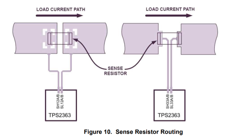
    The current limit setting of TPS2363 is dependent on the voltage across SH12A and SH12B which is the voltage across RSENSE.

    In your schematics, it is not very clear on the connections between RSENSE and SH12A/B (12VSENSEA/B). That is, the netlist 'P12V_GPU0_SENSE_P' is not shown as connecting to the RSENSE, R134. Is it a error in schematic ? Can you please share the entire schematics ?

    If the connection between RSENSE and SH12A/B (12VSENSEA/B) are correct as shown below, the current limit of 12V rail should be at 12.5 A because the RSENSE = 4 mohms.

    As you are not observing correct current limit behavior, please help with the following,

    • Layout file for review
    • Waveform capture during current limit test
      • Vin, Vout, Gate, Iin
      • Vin, Iin, C_FILTER, Gate
    • Change the IC with a new IC and perform current limit tests. This is to check if the IC on your board is damaged.