This thread has been locked.

If you have a related question, please click the "Ask a related question" button in the top right corner. The newly created question will be automatically linked to this question.

TPS543B20: PSpice for TI: TPS543B20 Floating Net Errors

Part Number: TPS543B20

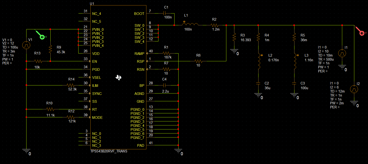
There are a number of pins on the TPS543B20 that I would like to float in my simulation.  however, when nothing is connected to these pins, PSpice throws an error due to these floating pins.  Is this an error in the model, or should I be doing something other than floating these pins for the purposes of simulation?  For reference, the pins I have floated are 3, 4, 5, 6, 31, 32, 34, 35, 36, and 37.

  • I was able to resolve the errors by attaching short wires to the pins I wanted to float.  This seems to make the IC happy and the simulation will start without errors.  However, I can't seem to get the part to turn on.  I have run the simulation model on the TPS543B20 page, and that starts up just fine.  I can't see why my simulation model is not starting.  My simple simulation:

  •  

    I don't see anything wrong with the schematic.

    How long are you allowing the simulation to run?  Your 12V supply V1 has a 3ms rise time, and the divider you have on EN wont enable the TPS543B20 until VIN reaches 8.8V, then there's another 512us delay from EN to the start of switching

    I will also look to see if I can find any other reason the part might not be starting.

  • Peter,

    My simulation profile specifies that the simulation should run until 15 ms, and that data will be saved immediately.  The input supply does ramp up as expected, and the current sources pulse in accordance with their specifications, but the output voltage never increases, and the switch node never pulses.

    You did mention the enable divider I have included which should delay the startup time slightly--interestingly, the enable pin voltage does not rise to the level I expected, and instead, it nearly follows the input voltage while rising until it is clamped just shy of 5 V.  I don't have any explanation for this behavior, but when the enable pin is directly connected to VIN, the overall circuit behavior is the same as I have described previously.

    I have attached my simulation file in case it is of any use in debugging this issue.

    TPS543B20_Rankin.zip

    Thanks,

    -Paul

  • Hi Paul,

    Try setting the Maximum Step Size in the Simulation Settings>Analysis tab to 50ns (enter 50n in the textbox) or lower. PSPICE may be skipping over too many time steps.

    Regards,
    Kris

  • Kris,

    I have tried running the simulation with those settings as well.  I tried that after looking for any difference between my simulation and the simulation provided by TI.  Although the simulation takes longer to complete after changing this setting, the result is the same--the converter never appears to be enabled.

    -Paul

  • Thanks for confirming, Paul.

    I have a feeling copying over and inserting the model from the simulation downloaded from the TPS543B20 product page will work, whereas the one inserted through the PSPICE for TI may have some issue.

    Let me know if you have tried that already, but I will try on my end tomorrow.

    If switching the model resolves the issue, I will let the PSPICE for TI folks know.

  • Kris,

    I tried that, but did not have any success.

    I did manage to get my simulation working.  I took the working example simulation and slowly changed components and connections one by one until it finally broke.  This simulation stopped working when I included a 121 kΩ resistor from MODE to ground.  I then went back to my original simulation (which is attached in a previous message), removed the 121 kΩ resistor, and tested the simulation again.  It started up as I would have expected (albeit with the same mysterious enable pin voltage behavior).  I will let the simulation run to confirm it works as expected.

    This solution will work for me for now, but I would like to know when these features will be added to simulation for this device?  I was interested to see the API/BB functionality in simulation, but now it would appear that I am unable to use it.

    Thanks,

    -Paul

  • Hi Paul,

    Nice work debugging this. Let me inform the modeling team on this. I confirmed your observation about adding the Mode resistor to ground.

    Regards,
    Kris

  • Hi ,

    I contacted the modeling team and they informed me that the API/BB feature is not supported by the model. The best way to evaluate the API/BB functionality at this time would be to test it on the evaluation board.

    Regards,
    Kris