This thread has been locked.

If you have a related question, please click the "Ask a related question" button in the top right corner. The newly created question will be automatically linked to this question.

LM7480-Q1: LM7480-Q1: Design review for Load dump test

Part Number: LM7480-Q1
Other Parts Discussed in Thread: LM7480, , LM74800-Q1

Dear Team,

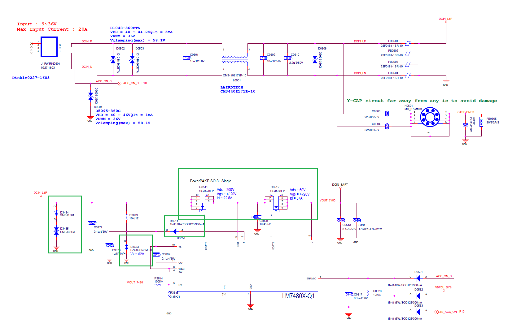
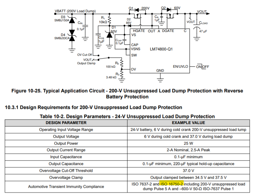
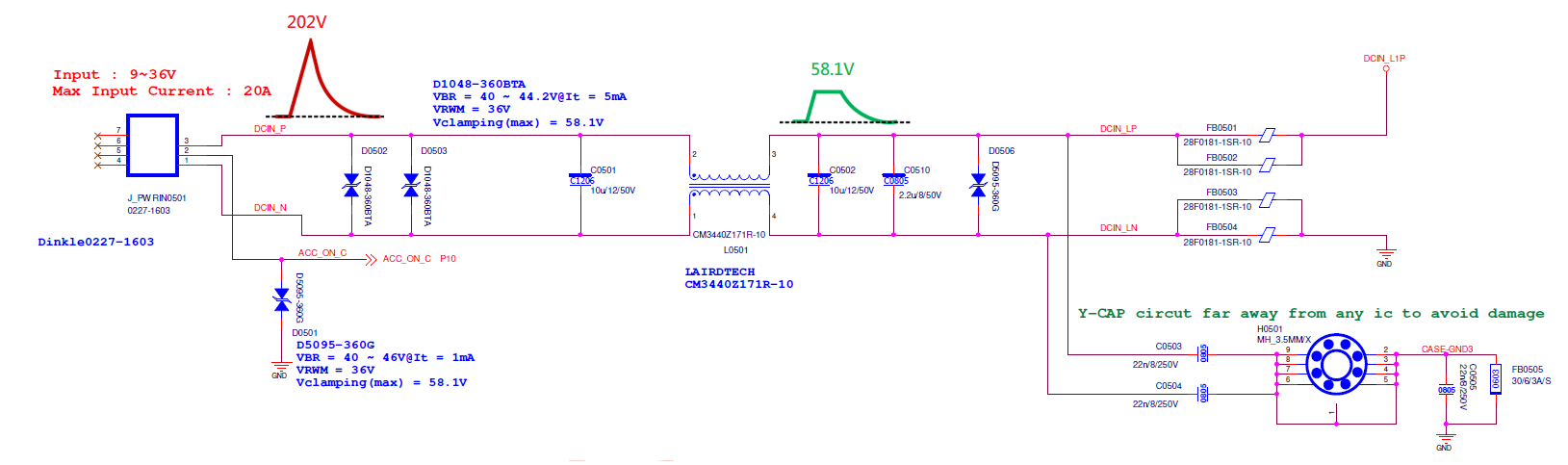
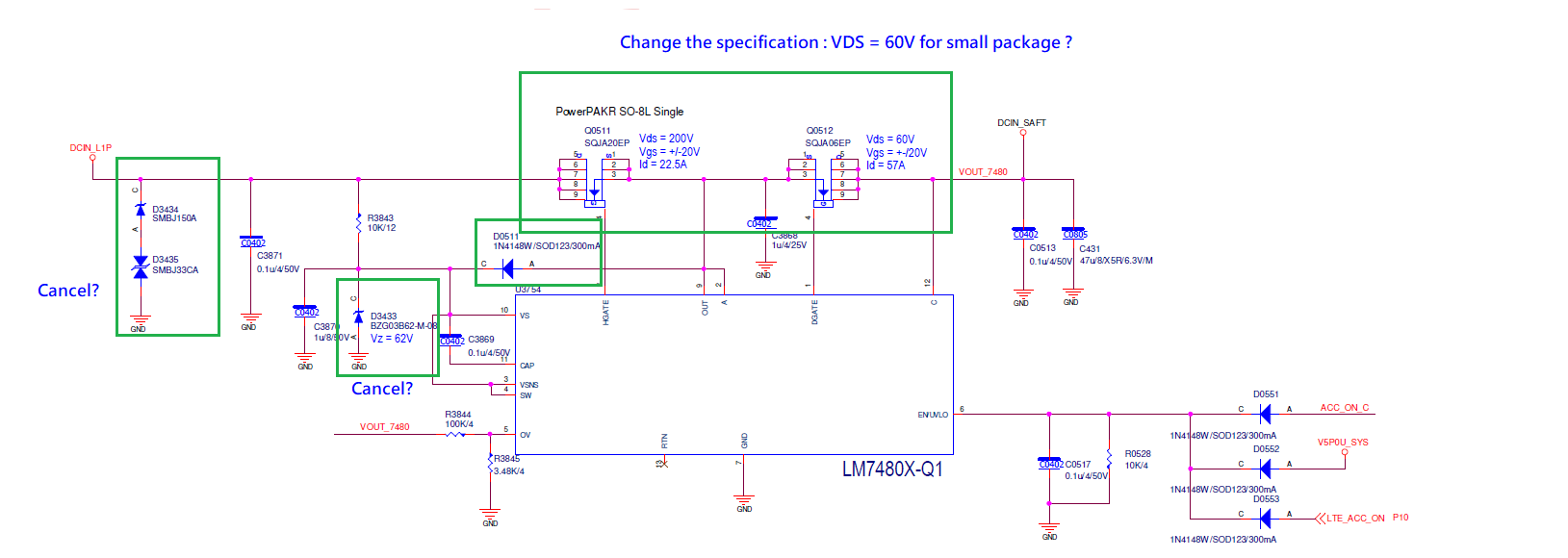
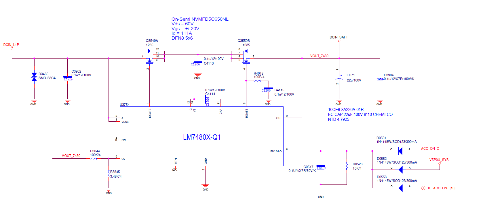
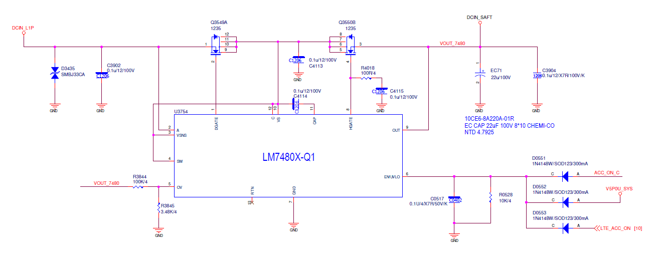
I finished the schematic just following the reference design, but I want to reserve the front-end protect schematic between DC Jack and LM7480.

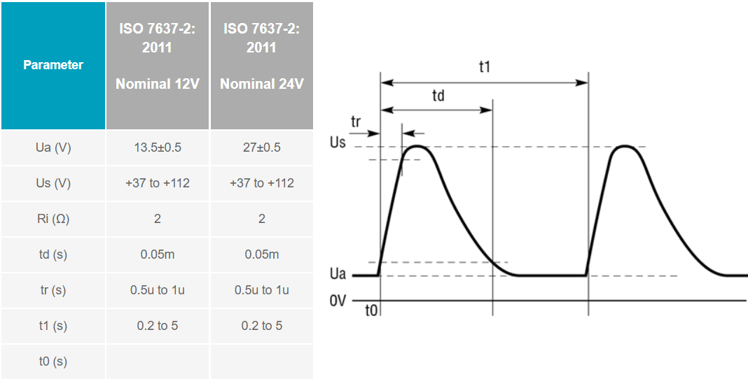
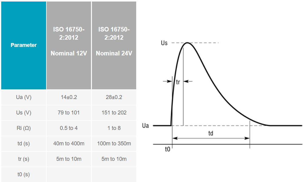
Please help me confirm whether the schematic is suitable for iso 16750-2 load dump test or it should remove/change some components especially the green block.

The following information is the specification of the system :

Vin : 9~ 36V

Max Input Current : 20A

Max Output Current : 10A

  • Hi Jerry,

    Welcome to e2e!

    Thanks for considering LM7480-Q1.  

    Please give me a couple of days before I review the schematics and get back to you.

  • Hi Jerry,

    The schematics look good to me. Looks like you have referred to section '10.3 200-V Unsuppressed Load Dump Protection Application' which is designed to support ISO 16750-2 including 200-V unsuppressed load dump Pulse.

  • Hi Team

    If I want to preserve the following design for transient pulse protection with ios 16750-2 5A and 5B.

    After confirmation, this design can clamp the voltage to 58.1V.

    Should I modify some components? To remove D3434, D3435 and D3433 or change the Vds to 60V of Q0511...Something like that...

    Furthermore, May I know the purpose of D0511?

  • Hi Jerry,

    Thanks for sharing more details. I will review and get back to you with my comments by 23rd Dec.

  • Hi Jerry,

    Do you mean the max voltage at DCIN_L1P will always be less than 58.1V and it is guaranteed by filter circuit before LM74800-Q1 ?

    If yes, then you can use the following circuit (common drain configuration) with lesser external components.

  • Hi Team

    Yes, it is guaranteed to clamp the voltage to 58.1V by filter circuit before LM74800-Q1.


    In other words, Is it guaranteed to pass iso16750-2 (especially 5a/5b) by using a common source configuration following the Figurate 10-25 of the datasheet without any protected schematic before LM74800-Q1?

  • Hi Praveen

    Just follow your suggestion using the common drain configuration.

    Please help me confirm whether the schematic is fine.

    In addition, should I leave SW pin floating?

  • Hi Jerry,

    In the common drain schematic that you have shared, please connect VS and C pins to the common drain point. 

    If the internal disconnect switch between VSNS and SW is not used then short them together and connect to VS pin.

    Regarding your previous question,

    The circuit in Figure 10-25 can be used to withstand ISO 7637-2 and ISO 16750-2 including 200-V unsuppressed load dump Pulse 5 A and –600-V 50-Ω ISO-7637 Pulse 1

  • Hi Praveen

    Thanks for your response.

    In order to make sure that I don't misunderstand what you mean, please kindly double confirm my schematic, thanks.

    Furthermore, the circuit in Figure 10-25 doesn't guarantee to withstand harsher tests such as 16750-2 load dump Pulse 5B or  ISO-7637 Pulse 2, right?

  • HI Jerry,

    In your schematics, please reduce the value of C4115 to 10nF. 

    Can you please provide more details (like waveforms and test conditions) about the ISO 16750-2 load dump Pulse 5B and   ISO-7637 Pulse 2

  • Hi Praveen

    Thanks for your confirmation.

    Regarding the test, please check the following description.

    You can find more detailed information at www.analog.com/.../ltspice-models-of-iso-7637-2-iso-16750-2-transients.html

    ISO 7637-2:2011 Pulse 2a

    Requirement: Pulse 2a must be repeated a minimum of 500 times. Class A through Class E operation is negotiated between the vehicle manufacturer and the equipment supplier, typically Class A.

    ISO 7637-2:2011 Pulse 2b

    Requirement: Pulse 2b must be repeated a minimum of 10 times. Class A through Class E operation is negotiated between the vehicle manufacturer and the equipment supplier. Since the power is effectively removed during the test, it is usually defined as Class A if the equipment returns to normal operation without user intervention after power is reapplied.

    ISO 16750-2 5A  “Test A – without centralized load dump suppression”

    Requirement: Ten pulses at 1-minute intervals. Class C.

    16750-2 5B “Test B – with centralized load dump suppression”

    Requirement: Five pulses at 1-minute intervals. Class C

  • Hi Jerry,

    Thanks for the detailed explanation. I will get back  to you  by tomorrow on your question on if common source topology in Figure 10-25 can withstand  harsher tests such as 16750-2 load dump Pulse 5B and ISO-7637 Pulse 2.

  • Hi Jerry,

    We can confirm that the Common Source topology in Figure 10-25 can withstand harsher tests such as 16750-2 load dump Pulse 5B and ISO-7637 Pulse 2 without any external Filter. The external filter may need to be added as per the EMI/EMC system level requirements and challenges. 

  • Hi  Praveen

    Thanks for your response, have a good day.