Hi team,
Good day.
Our customer needs assistance with the situation they were encountering in using the TPS61500. Please help with the PCB and schematic review. Here are the details provided to us.
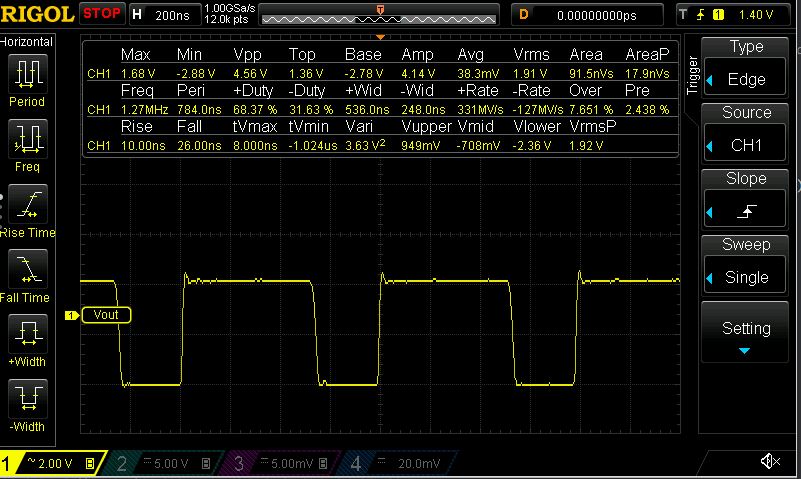
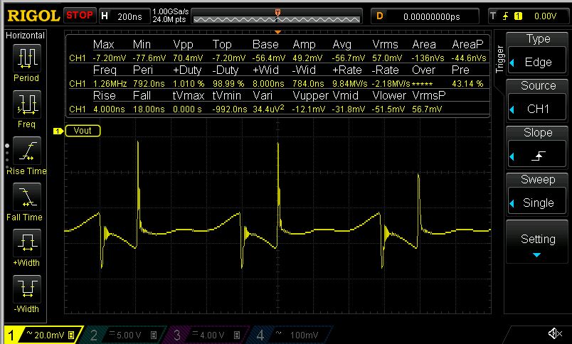
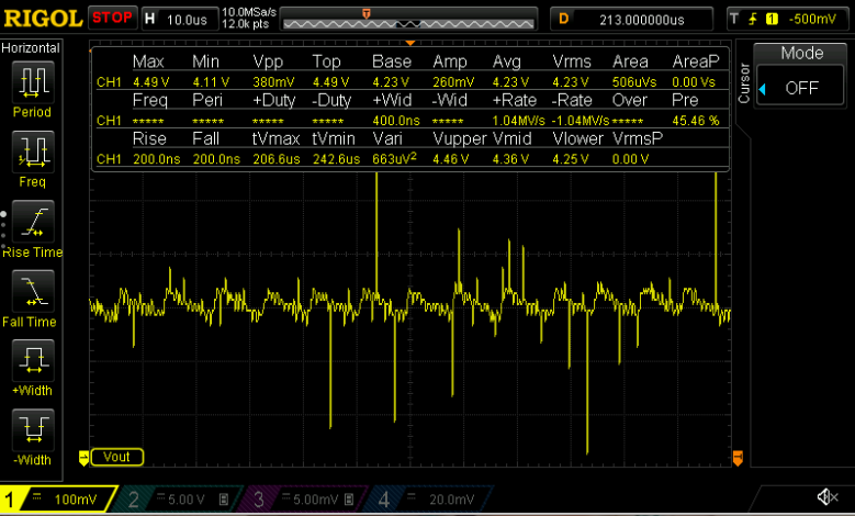
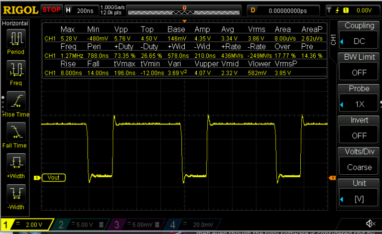
"I wanted to contact you because I have a suspicion that I was sold some defective TPS61500 3A Boost constant current ICs from one of your suppliers, LCSC. I have tried changing everything on my design from inductor values, output capacitors, switching frequency setting, Current set resistor value but to no avail. The IC doesn't seem to supply more than 1.3A. Although I do have to point out that it seems to be working properly for lower currents of approximately sub 800mA.
I have put together quite a few boards but they all seem to have the same Issue. I ran the formulas in the datasheet for calculated max output current and I am getting a calculated max of 2+ A. Furthermore the waveform on the oscilloscope doesn't look all that great and it differs vastly from the one in the datasheet. Testing conditions are as following: Voltage on the Input: 3.91V RMS, Output voltage 4.52v RMS. Frequency set resistor 100killo Ohms, Voltage divider values for OVP 120k and 21k Ohm resistors respectively. Inductor value is 22uH with an Isat of 3A from Panasonic. Current set resistor is 0,095ohms. Diode is a DIYI brand 5A 40v 225mv measured drop SBD. Output cap configuration consists of 5 4.7uF 1206 size TDK X7R capacitors rated at 50v. Soft start capacitor is a 22uF TDK 1206 cap rated at 10v. All of my components including the TPS61500 are from LCSC. "
Attached is the schematic and PCB layout. Thank you for your assistance.
Regards,
Carlo