


Hello,
I am looking for a hint debugging the BQ25866 charging circuit. After connecting the power adapter STAT diode blinks once about 1s and then starts blinking about 5Hz. After that goes black. And the battery isn't charging.
What is suspicious for me yesterday it worked.
For me, it looks like VBUS overload but I don't know where to look for the short-circuit as far as it appears only when it is checking the power source. When I connect the power adapter without the battery connected, STAT goes low stable, I connect the battery then and it is charging but only 270mA. Yesterday it was ca. 1A.
Current and voltage settings:
ISET R = 600R
ICHG R = 8K2
VSET R = 150K
Oscilograms:
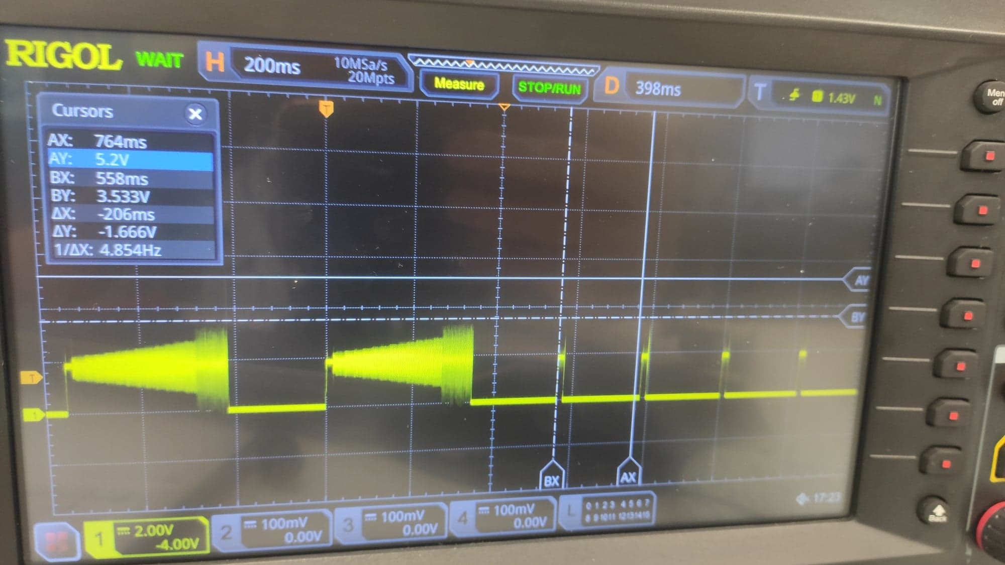
STAT (Diode anode):
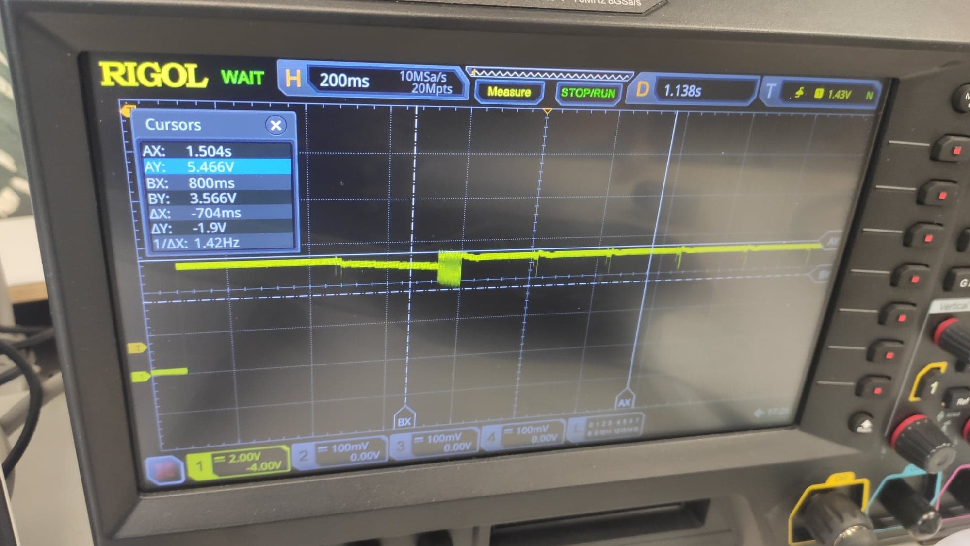
VBUS:
Best regards
Adrian Barnaś
