Dear support team / Dear Community,
We have a problem concering the TPS61500. Below you will find a description of our project and our problem.
We are working in a project for a diploma thesis. The goal of this project is to build a lamp which is able to emit light in most colors of the RGB- model.
To achieve this goal we are using three differnt types of high power leds as illuminants. Each Type emmits light in a specific color. In our case they emit light in red, green and blue. These colors will be added together and produce a new color.
We have successfully implemented a circuit to dim three Osram Golden Dragon high power LEDs. (one each for red, blue and green)
The next step in the project is to implement a new circuit to dim 10 LEDs for each color to iluminate a bigger area. To accomplish that objective we have searched for a LED driver based on the following criterias:
* output voltage must be high enough to power 10 LEDS (1 LED: 3.43V forwarding voltage, 0.7A current)
* brightness dimming, which should be defined by an external PWM signal (pure PWM dimming)
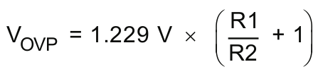
* overvoltage protection
* input voltage between 5V and 20V
After a lot of research we found the device TPS61500 (See datasheet: http://focus.ti.com/general/docs/lit/getliterature.tsp?genericPartNumber=tps61500&fileType=pdf).
The following values are based on the datasheet:
* 2.9-V to 18-V Input Voltage Range
* 3-A, 40-V Internal Power Switch
* Analog and Pure PWM Brightness Dimming
* ...
In our opinion this device should perfectly meet our needs.
So we designed our circuit based on the "Typical Application" Figure 2. Pure PWM Dimming Method. Here is the schematic of our application:
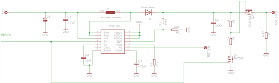
Description of the Schematic:
* The LEDs are mounted on a seperate print and are connected serially.
* The PWM Signal is assigned to the PIN 4 (EN) of the TPS and to the FET Q1.
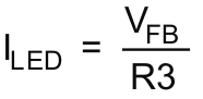
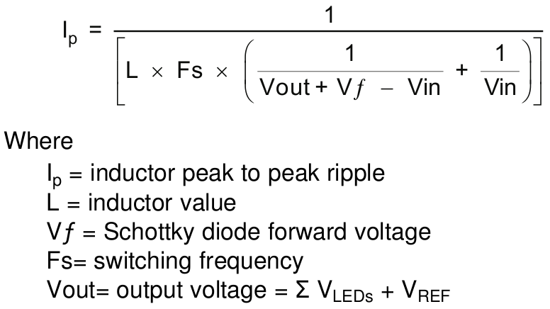
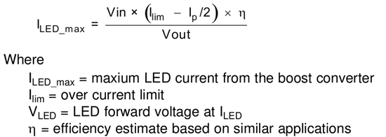
According to the datasheet the following values were calculated (a detailed description can be found in the datasheet on the pages: 10-14)
* C1: 4.7uF
* C2: 1uF
* C3: 47nF
* C4: 470nF
* C5: 100nF
* R1: XXX
* R2: YYY
* R3: 0.27
* R4: 51k
* R8, R9: 1k
* L1: VLF10040 - 6R8N4R5: 6.8 uH
* D1: Schottky-Diode 30BQ040
* Q1: 2N7002
* Q2: Si2319DS
Our main problem:
In our setup we have a Vin of about 12V and a Vout of 36V. While we tested the circuit we noticed that the output voltage is not high enough to power 10 LEDs. The output voltage was as high as the input voltage. For that reason the LEDs aren't iluminating any light. Therefore we assume that we have a mistake in the part of the circuit where the TPS61500 scales the voltage up to Vout.
Things that were tested and worked as they should:
* Selection of the switching frequency: R4 = 51k which sets the frequency to 2MHz
* Switching of the FETs Q1 & Q2
At this point we are stuck and hope that you can help us to solve our problem and help us to finish our project in time.
We really appreciate any help and are looking forward to hearing from you soon.
If there are any questions according to the Text above feel free to contact us at any time. You can either write an answer in the forum or send me an email to
"andreas.pabst@sz-ybbs.ac.at"
Thankfully,
Andreas Pabst