This thread has been locked.

If you have a related question, please click the "Ask a related question" button in the top right corner. The newly created question will be automatically linked to this question.

BQ34Z100-G1: Unsuccessful Learning Cycle

Part Number: BQ34Z100-G1
Other Parts Discussed in Thread: GPCCHEM, BQ34Z100, BQ34110, BQ34Z100EVM

Hi TI expert,

I am using BQ34Z100-G1 to monitor a 12S NiCD battery. The capacity of battery is about 7AH. Energy 168WH. Chemistry ID 6103. And I run a learning cycle (charged to full--> wait until RUP_DIS goes 0, OCVTAKEN turns high  --> discharged to empty --> wait until VOK goes low and OCVTAKEN high) yesterday. However, I meet a few issues here, please help me out.

1.  after a discharging cycle, the learned status was not updated to 5 when the OCVTAKEN is high and VOK reset. I saw in the "4863. How to Completed a Successful Learning Cycle", it states that sequence of learning for the NiCD battery is: charge to full -- > discharge --> charge to full --> discharge, which is different from LI-ON battery. Is the learning status supposed to be updated in the relax time of discharging? 

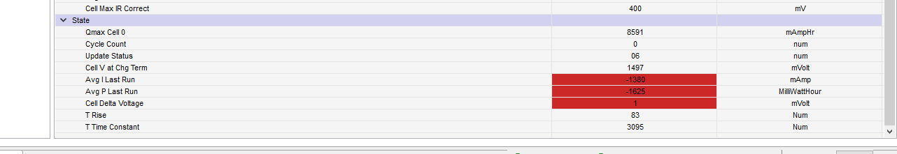
2. The True RC goes negative when it is closed to the end of discharging cycle. And then in relax, it jumps to -3427 and the True FCC jumps lower as well. What could be the reasons for these behavior? (Main problem)

3. Does the charging or discharging current affect the result for NICD battery? It suggests to use C/5 to C/2 current to charge the battery, what if I use C/7? The default charger I have can only charge up to C/7. Another charger has issue when charging the battery, the current drops to 0 once a while. I am not sure why. 

4. I saw in some posts which say the Design Energy is the for each individual cell, so I divide 168WH/20 = 8400 mWh for the design energy and make the energy scale to 1. Is it right? The design energy here is cell based or for the whole battery?

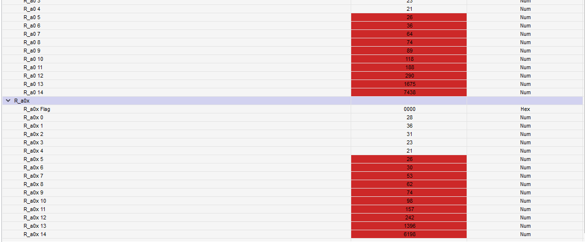
5. In the original post, Batt stated that "The log shows unusually disjointed values from the test. The jumps are 20mV each." at the end of post. I got the same voltages in the log, jump 20mV each, is there anything wrong with this behavior?

I have attached the configuration file and logging file. Please help me have a look.

Thanks

2476.NICD.rar

  • Anyone could help me with this?

  • Hi Charles,

    We will get back to later today.

    Thanks,

  • Hi Charles,

    There is some drain on the battery during the final relax, this may prevent OCV reading from being taken required for qmax update.

    How many cells are in parallel here? 

    Best regards,

  • Hi Nick, 

    Thanks for your reply. Just one cell in parallel. 20 cells in series.

    There is nothing connected to the battery at relax time, except the battery monitoring board. How do you know there are some drain at relaxing time after discharged? Could you please tell me which register indicates that?

    My main concern is the reason True FCC and True RC jump lower suddenly when OCVTAKEN sets during relax time. I just took over this project recently and people worked on it before me had the same issue which was not resolved.  I believe there is something wrong with the configurations, I just changed the design energy to 8400 mWh. I am not sure if there are any other mistakes on the setting, please help me have a look on the configurations.

    Thanks,

    Charles

  • HI Charles,

    We will look into this and give you an update within a week.

    Best regards,

  • Second Trial.xlsx

    Hi Nick,

    Just giving the updates I have. I run another two full cycles and the learn status changed to 0x06 successfully. However, same as before, the true RC jumps to negative value during the rest time after discharging. It happens right at the learning status updated. The Qmax Cell 0 value seems right after first and second learning cycles. I have attached the new logging file. Please help me with it.

    Please only look at sheet1 of this file, sheet2 are just extra logs taken over the weekend, which I think are not necessary.

    Thanks,

    Charles

  • Hi Charles,

    Design energy should be the total capacity of the pack, in your case 168WH.

    Best regards,

  • Hi Nick,

    That's odd. I have seen in several posts, the supporters said it is for cell energy. Like this one, 

    Also, people worked on this project before me did use 168WH with energy scale of 6. However, they also had the issue with true RC and true FFC. True RC always jumps to negative values during relaxing time. And FFC then becomes much smaller value.

    Could you please tell me how the true FFC is different from Qmax cell 0? How come one of them is correct while another one is wrong?

  • Hi,

    Anyone can help me out? 

  • Hi Charles,

    The post you linked is correct, sorry for misleading info.

    What are you looking for TI to address?

    Thanks,

  • Hi Nick,

    Could you please help take a look on the configuration file and the logs? We really got lost here. I just would like to know why the True RC and True FCC drop down as soon as the status updated. Meanwhile, Qmax cell 0 stays at correct value. We need the parameters of full charge capacity and remaining charge capacity in our design, so the True RC and True FCC have to be correct before generating golden image file.

    Thanks,

    Charles

  • Hi Charles,

    We are looking into your files and will get back within the week.

    Thanks,

  • Hi Charles,

    Can you upload the report from GPCCHEM?

    Thanks,

  • Hi Nick,

    I have uploaded a package including the data we submitted to the the GPC for the chemistry ID. Please find the "GPC_report.txt", which is the report from GPCCHEM,  if you don't need other files.

    Thanks,

    Charles

    8507.NiCad_battery_test-report.zip

  • Hi Charles,

     Your ChemID deviation is ok. We have looked at your files and are still working on determining root cause. 

    You can try setting the load select to 2 and rerunning the learning cycle. Make sure the chemID from report has been programmed first.

    Best regards,

  • Hi Nick,

    Thanks for your help. I will change that setting and run two complete learning cycles again,

    Regards,

    Charles

  • Battery Test - 2.xlsx

    Hi Nick,

    I run one cycle after changing the "load select" to 2. However, I cannot see any changes, the True FCC and True RC drop again when the status updated to 5. I attached the logging file for reference.

    Do you have any luck in analysis of my previous logging file?

    Thanks,

    Charles

  • Hi Charles,

    Our algorithm team is looking at this one.

    Best regards,

  • Based on the overall discussion it looks like the issue is with not detecting the end of charge. For NiCd and NiMH the OCV reading at the end of charge is not very reliable because of strong hysteresis so the gauge instead relays of having FC bit set by satisfying charge termination condition. Since charge termination for NiMH is based on dV/dt detection, it will not be satisfied in simple constant current charging that happens with NiCd in this case.

    I suggest to get learning cycle by alternative means, by using the golden image tool below. Please follow the direction of the instruction manual for preparing the data and uploading it to the tool. 

  • Hi Yevgen,

    Thanks for your efforts. For NiCd battery, does the charge current matter? I do have a default charger for the battery, which can only provide around C/8 current. It might be able to have charge termination based on dV/dt. In all bq34z100 instructions, they suggested to use charge current between C/5 to C/2, that's why I haven't tried the default charger.

    Thanks,

    Charles

  • Charles,

    since dV/dt based termination happens due to increased self-heating at the end of charge, which results

    in decreased I*R rise, it is usually more prominent at higher currents. So C/2 would be better then C/8. But in general

    dV/dt is less prominent in NiCd compaed to NiMH so it would be hard to detect, in which case I would recomend to use submiting

    the data to the GPC tool. GPC tool is not as picky about charge termination, it will just assume that it was terminated at fully charged state.

    Regards,
    Yevgen

  • Hi Yevgen,

    Thanks, I will try with this GPC tool soon. 

    Regards,

    Charles

  • Hi Yevgen,

    Thanks for your recommendation. With the calculating tool, he True FCC and True RC issues seem okay now. However, I found another issue now with the new Golden image file, I will run the testing cycle a couple more time and see if I will get different Ra values. In the same time, I would like to describe the issues, maybe you have seen that before. 

    With new golden image file loaded, when the battery is in charge or discharge, if I disconnected the gauge from the battery and reconnected them after for a minute, the state of charge (wrong remaining charge capacity) is really off (usually much higher than it supposed to be). For example, I charge the battery for a few minutes, and the state of charge goes to 1%, then I disconnect the gauge and reconnect soon, the state of charge might jump to 30% or 40%. I have attached a short logging file which shows this phenomenon. State of Charge Issue.xlsx

    Thanks,

    Charles

  • It looks like there was some issue with the number of serial cells settings. Can you send the zip file you used to submit the data to the tool, so I can check that serial cell setting is matching actual voltage in the column as well as other settings?

    Regards,

    Yevgen

  • Hi Yevgen,

    Thanks for your reply. I have included the zip files which I submitted and the GPC tool reported. The number of series cells is 20, no parallel cell. And the battery capacity is 7AH and 168WH.

    Regards,

    Charles

    GPC Golden GG Maker.zipGPC Golden GG Maker-report.zip

  • I checked the data and everything looks correct. Regarding your question:

    >With new golden image file loaded, when the battery is in charge or discharge, if I disconnected the gauge from the battery and reconnected them after for a >minute, the state of charge (wrong remaining charge capacity) is really off (usually much higher than it supposed to be). For example, I charge the battery for a >few minutes, and the state of charge goes to 1%, then I disconnect the gauge and reconnect soon, the state of charge might jump to 30% or 40%. I have >attached a short logging file which shows this phenomenon

    This gauge is intended to be permanently connected to the battery, so that it can take advantage of coulomb counting and voltage correlation when condition for each is the best. For example it would not take voltage correlation readings immediately after charge because there is a very large voltage hysteresis present. So disconnecting and reconnecting the gauge will certainly cause abnormal behaviour - in this case SOC will get higher because voltage after charge has hysteresis (higher) then after discahrge.
    It should also be only connected when battery is well rested, since relaxation time after charge and discharge is on order of hours.

    Just make sure to never disconnect the gauge from the battery. First connection is best done when battery is at rest (more then 2 hrs) after some discharge period. Rest after partial charge would need to be much longer, over 24 hrs to fully remove effects of hysteresis, so it best to charge to full and give at least 5hr of rest if initialization need to happen after charge.

    Regards,

    Yevgen

  • Hi Yevgen,

    Thanks a lot for your information. In our design, the chip will be off when the device turns off. Therefore, It doesn't connect to the battery permanently. Do you know any other TI battery gauges would be suitable in our case? And it would be best if was designed to monitor NiCd batteries. I only saw BQ34110, which might work for the NiCd battery, but I am not sure how accurate it would be. Because I saw in other tickets, the BQ34Z100 is more accurate and is good when battery is aged.

    Best Regards,

    Charles

  • The other TI gauges use coulomb counting, so they are even more dependent on being permanently connected to the battery.


    Even though it is not a standard usage, In principle you can use this gauge, since it does have voltage based  initialization, but you will
    need to make sure that it turns ON (initializes) only before the load is applied to the system so that it can take a well relaxed OCV reading.
    This might requires some management from the side of your main system controller - you would turn on the gauge first, take OCV reading
    to init, and only then enable main device function that draws large loads.

    You would also need to keep it on for 2-5 hrs after the main load stops in order to update Qmax, since it requires fully relaxed voltage, detected by dV/dt 
    condition, to have full functionality of Qmax update.

    If you are just planning to use it for very rough estimate of SOC that does not involve Qmax update, above is not needed, but accuracy will decrease
    if no actual Qmax update take place, as true Qmax will decrease.


  • Hi Yevgen,

    Just another 2 quick questions about the gauge.

    1. If I generated the golden image file when the learn status goes to 6, and then I connected a battery permanently to the gauge loaded with this golden image. Are the parameters, such as FCC, RC, and QMAX etc., going to be updated after some charging and discharging cycles? If so, the gauge stops learning when the status is 6, are the updates based on the chemicals changes in the battery? 

    2. I saw in the datasheet, there are some registers storing life time logging data. Do we need to turn it on to make the gauge more accurate after it getting aged? Or turning it on just to update lifetime max and minimum values in the registers, but not to affect the other parameters?

    Thanks,

    Charles

  • 1. Update Status 6 just indicates that first learning took place, so the GG file can be used to make golden image for mass production. Pack will continue updating Ra and Qmax in the field even after that.


    2. Lifetime data is just needed for debug and quality control purposes that manufacturer can analyze after the pack is taken back from the field. It is not by itself used for gauging purposes, so turning it on has no effect on other gauging or parameters updates.

    Regards,

    Yevgen

  • OK. Thanks a lot for your help, Yevgen. I will update this thread as "issue resolved".

  • Hi Yevgen,

    After a few more days tests, I found the issue is still not resolved even with gauge connected permanently. With the golden image file from GPC calculator, it is only good for one continuous discharging cycle. 

    I stopped the discharge process when SOC is at around 20%, then I waited there for about one hour until the OCVTAKEN bit is set. The FCC and True RC jump around again like before. SOC jumps from 20% to 48% (line11218).

    Then I continued to discharge the battery until empty, and wait for another hour until OCVTAKEN bit is set. Now the FCC drops and True RC goes to negative again (line 12861), the result is same to what I have done before using the cycle learning process. The FCC and True RC start dropping since line 11476 when voltage is at 24.2V, because it was popping up from 20% to 48%.

    At the end of discharging cycle. I realized that the AVG I Last Run and AVG P Last Run are updated from -299, -1131 to -1380, -1625, respectively. Even though the values in Ra Table are updated as well, it seems they are not affecting the FCC and true RC that much. If I changed AVG I and AVG P back to -299 and -1131, then disconnected and reconnected the gauge from the battery, the FCC and True RC goes back to values that seems to be correct. And it becomes incorrect values again if I changed them to -1380, -1625, which are the actual average current and power run from last discharge cycle.

    I am trying to change the learn status from 6 to 2 to prevent updating the QMAX and Ra values, even though it doesn't seem to be right approach for our application to disable the Ra and Qmax learning, but I guess it still cannot stop changing of AVG I and AVG P. 

    I also tried to modify the values AVG I Last Run and AVG P Last Run on gg file and resubmit the package to GPC calculator tool, however, it seems these two parameters are not affecting Ra values. The GPC calculator tool might have some issues since last evening, because it keeps rearranging the texts on the top few lines in the GG report file. 

    Please help me out.

    Thanks,

    Charles 

    Logging Jan 26.xlsx

  • From the above data there are not indications that Ra and Qmax are abnormal, so I would not try to prevent their

    update. 

    Also the value of current that is learned is correct, according to your discharge rate. In any case, you do have an option to make value used for simulation of RemCap and FCC fixed - you can set Load Select = 6 (custom), Load Mode = 0, and set User Rate mA to desired value, for example -299mA. 

    The only value that is not updated and could contribute in too strong effect of current on RemCap and FCC are the thermal modeling parameters.

    Temp_k and Temp_a. If data summited to the tool did not have temperature correctly measured on the surface of the cells, temp_k might be incorrect. You can for testing try to increase it by 5x, and see if this will prevent RemCap and FCC from becoming too small. 

    If that is the case I would re-collect the data at the same rate you are using for the testing, so temperature increase is significant to update temp_k and temp_a parameters, and after making sure thermistor is connected to the cells.

    Regards,
    Yevgen

  • Hi Yevgen,

    I guess the thermal modeling parameters have high possibility to cause the issues. Our battery is well packed, so there is no way to measure the cell temperature, there is an NTC wire from the internal of the battery, but I didn't connect it to anything. Also, I cannot find the temp_k and temp_a parameters on the data memory. Are you referring some parameters in the Ra table? Sorry, I am not familiar with the thermal part parameters, I could not find much information in the datasheet.

    The board I am using is BQ34Z100EVM, which has one thermal sensor, I guess the user has to put the battery cell very closed to this sensor to get accurate temperature. In our case, where should I connect the NTC wire on the board. Should I remove that 103AT-2 thermistor and connect it directly to pin P6/TS?

    Best Regard,

    Charles

  • Hello Charles,

    I would not recommend using the thermistor in the pack because it most likely has different characteristics from the semitc 103AT we recommend.

    You should extend the wires for the thermistor to the pack.

    Sincerely,

    Wyatt Keller

  • Hi Wyatt,

    Do you know the Temp_k and Temp_a parameters Yevgen mentioned? I could not find them in the data memory of BQ34Z100 chip, I would like to have a test by changing these values as per Yevgen suggested.

    Thanks,

    Charles

  • Hi Wyatt,

    I understand that the thermistor probably is different from semitc 103AT, however, the battery we are using have battery cells well isolated from outside environment. I could not put another thermistor inside the battery. I just would like to try to see if it works, if it doesn't, we would need to switch to another monitoring chip. 

    In the datasheet, it states that "When an external thermistor is used, REG25 (pin 7) is used to bias the thermistor and TS (pin 11) is used to measure the thermistor voltage (a pull-down circuit is implemented inside the device). The device then correlates the voltage to temperature, assuming the thermistor is a Semitec 103AT or similar device."  I am wondering if I connect one NTC wire to the TS pin, what should I do for the REG25 pin? leave it floating?

    Thanks,

    Charles

  • Hello, I also encountered the problem that Ture FCC is much less than the actual capacity, did you solve it?

  • Not yet. In my case, I think I don't use the thermistor properly.