This thread has been locked.

If you have a related question, please click the "Ask a related question" button in the top right corner. The newly created question will be automatically linked to this question.

LMZ23610: DC-DC SWITCHING REGULATOR COMPONENT DAMAGE WHEN REPLACED ON PCB

Part Number: LMZ23610

Dear sir/madam,

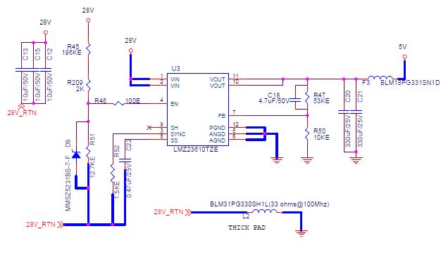
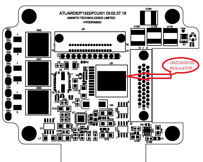
i found an issue for lmz23610tze DC-DCregulator while replacing on the boards.There is no short found on board when placed for 1st time on PCB but when replaced for second time the component is getting internally shorted like feedback pin no7 and ground pin5 getting shorted with 14.4ohms resistance on one board.In another board the component is getting internally shorted like supply pin 1 and ground pin 5 shorted with 1ohm resistance. this short/resistance is observed by lifting the above mentioned  pin numbers.AS even i measured on PCB between those pin number and does not found any short on board.

  • Hi Roshan,

    When replacing the device, can you make sure that the pins do not have residual solder that could potentially create a bridge that shorts the pins together?

    Also how are you replacing the device (reflow profile, temperature. etc.)? 

    I haven't had an issues reflowing these NDY leaded power module devices.

    Regards,

    Jimmy  

  • DEAR SIR,

    When replacing the device, we are sure that the pins do not have residual solder that could potentially create a bridge that shorts the pins.

    When replaced the device temperature maintained on PICK AND PLACE SMD machine is 250-300 degrees and manually soldered maintained temperature is 200-270 degrees.

  • Hi Roshan,

    Just to clarify, you don't have any issues with the standard operation of the device once the device is assembled and powered up? The failure issue only occurs when you are removing the device from the board and reflowing the device a second time onto your PCB?

    Since you are sure that there is no residual solder on the pins, I suspect the issue here is caused during rework/reflow process. 

    I'd caution you to limit/control your maximum temperature following the sample reflow profile in Figure 60. Notice how the reflow profile has the be peak temperature around 242.5degC. Is it possible that during your removal and second reflow, the heat is not controlled and damaging the device? 

    Regards,

    Jimmy 

  • Dear jimmy,

    yes we dont have any issues with the standard operation of the device once the device is assembled and powered up,yes failure occurs only when removing the device.

    yes there is no residual solder on the pins.

    As mentioned before we maintain 250-300 degress for replacing.if  heat is the reason for component damage  can u please give us  any suggestion ?(as we could maintain only 200 above temperature for manual soldering and 250 degrees and above for smd machine )

  • Hi Roshan,

    When the boards are being made, I assume they go through the SMD machine flow. Are the ohm measurements of the shorted pins from a loose unit that has been removed from your board (ie. probing the module's pin with multimeter)? 

    Again I'd like to highlight Section 10.4 in the datasheet that shows both the recommended reflow temperature profile and quote "maximum number of reflows allowed is one". Subjecting this device through multiple reflows may be causing internal damage on the device and could be resulting in the failure condition you are seeing.

    If there is no operational issue with this part, can you help me understand why you have to remove the device off your board and subject the device to 2 additional reflow process (1 for removal from board and 1 for mounting onto board)?

  • Dear jimmy,

    We observed for one board current drawn to be more like 0.25A(how much we set the dc voltage and current that much current is drawing) when disconnected from next section.So we lifted the pins of REGULATOR that is 7th pin and ground pin and found 8.6ohms resistance between them then we decided to replace the component ,after removing the component  also we checked and found short.for this board at present we are connecting 5v dc externally and the board found to be working in good.

    there is no 2 additional reflows  because as we removed the damaged one from board and placed another new component on board(exposed to temperature 1 time only for mounting on board) then we found the issue as i said before.

  • Hi Roshan,

    Can you provide PCB layout and schematic for review? Also what is your initial operating conditions(VIN,VOUT,IOUT)? Depending on this that 0.25A current drawn may be expected. Please provide waveform on VIN,VOUT and IOUT at steady state operation to confirm proper output regulation.

    Again as you've previously stated "yes we dont have any issues with the standard operation of the device once the device is assembled and powered up,yes failure occurs only when removing the device." I take this to mean that there should be no issues with output voltage or input current drawn at normal operation.

    When you say connect 5V DC externally, I assume you mean 5V input supply? 

    Regards,

    Jimmy

  • HAI JIMMY,

    PFA, YES AS REGULATOR GOT DAMAGED I AM USING THE BOARD BY EXTERNAL CONNECTION OF 5V SUPPLY.

  • HAI JIMMY,

    NORMALLY WHEN BOARD IS WORKING GOOD IT DRAWS 0.08-0.10A OF CURRENT EVEN AFTER LOADING THE PROGRAM .

  • Hi Roshan,

    What is your expected output load current (IOUT)? It looks like you are doing a 28Vin|5Vout application. The schematic and PCB layout doesn't look abnormal so I don't think it's anything in that aspect. 

    Can you provide waveform of VIN,VOUT,IOUT at steady state operation? I'd expect your efficiency readings to follow Figure 1 for a typical 5Vout at 25C condition. 

    Again I just want to confirm that there is no loss of function/operation at steady state operation. Issue only happens when you remove the device. If this is the case, then the only thing I can think of is the removal process might be damaging the part... 

    Regards,

    Jimmy 

  • hai jimmy,

    our expected load current is 943.6mA on 5V OUTPUT.As we  didnt have the images but when we connect the board because of regulator internal short the voltage getting drop in powersupply to 0.01v and  the current drawn to be high as given input from supply.IS THERE ANY OTHER THING TO RESOLVE ISSUE THAT  YOU COULD SUGGEST US?

  • Hi Roshan,

    How many of your boards have this issue?

    One suggestion: Is it possible to get a new board with a new LMZ23610 device populated on the board and retest? During retest please have stable power supply connected to the CIN and output load (preferably an e-load) connected to the COUT. Then you can connect your downstream load which will pull your expected 943.6mA of current and retest for efficiency and output regulation. I'd expect it to be the same as the e-load.  Doing this will exercise the LMZ23610 device and check for proper operation at both ideal conditions and your application condition.  

    Regards,

    Jimmy 

  • hai jimmy,

    the expected load current is 600-940mA,for one board we observed input voltage to be 28v and output voltage is zero and on feedback pin also zero is found,for another board if we try to on the board the voltage on supply drops to 0.09v and current increases to 0.48A

  • Hi Roshan,

    Right now it is not clear to me whether the issue is device/unit related from manufacturing or post-reflow/heat related. 

    Because of this, I want to reinforce this idea that we should test a new board with a new unit straight from assembly to get an accurate understanding of the power up and steady state operation of the device on your board. The new unit should not have any reworks done on it (ie. lifting pins etc.). This will exercise your board's operation with a device unit straight from the reel without any external modification that can be a factor in the failure you are seeing. 

    Can you confirm this issue (ie. output voltage not regulating) is present on a new device/new board without any modifications at no load and then at your desired 940mA load? If you have not done so, please provide updates on this. One extra step you can do is to do a pin continuity test on the device to verify that the device doesn't have existing internal shorts prior to mounting onto your board. 

    If the device is operating correctly, I would expect the efficiency to be somewhere around between 70-75% for a 28Vin|5Vout|1A|25degC ambient application. This is an approximation using the existing Figure 1

    Regards,

    Jimmy 

  • Hi Roshan,

    I have not heard back from you for some time so I will assume you were able to resolve the issue on your end. 

    This thread will be closed for now. If you have any further questions please reply to this message and it will reopen for further discussion.

    Regards,

    Jimmy