My customer asks:
"I use bq24086 for a charger and am having trouble with deeply discharged batteries. Everything works fine on normally discharged batteries, but the system must be able to recover from a deeply discharged state (i.e. after the product has sat on a store shelf for months, or if the user depletes it and does not use it for a period of time). So that’s what I’m testing. My battery terminal voltage is 2.7V and I have disconnected any load on the circuit. I have a current meter (set at 1A range for minimal resistance) in line with the battery to monitor charging current. I’ve got an oscilloscope looking at battery voltage. The charge current on the 24086 is set at 650mA. Without the charging voltage plugged in, the current meter shows -50uA (small discharge into the circuit). It changes to 73uA (small battery charge current) when I attach 5V charging voltage. The battery voltage remains at 2.73V. If I switch in the circuit, the battery current changes to -50mA to power the circuit and the voltage starts dropping. If I disconnect the battery, the charger enters the battery absent state (observed on the scope). So the bq24086 is staying very resistive. It won’t supply any current to the application circuit, and I don’t think it’s outputting enough voltage to deactivate the low battery protection in the Li-Ion pack. Is there anything I can do to force the 24086 to output more so that I can get my system running (enough that the micro can run in low power mode and keep everything off until the battery charges above 3V) and have the battery charge? I’m going to leave the charger running over the weekend to see if the battery will eventually get high enough. Update: This is a show stopper and has four different products on hold as a result because they all use the same circuit.
I changed the charger to “LDO” mode (removed the TMR resistor) and bypassed my selectable charge rate so RSET is now 1k for about 450mA.
The main circuit attaches to the battery charger board through a connector, so I can easily check if just the charger works. It does.
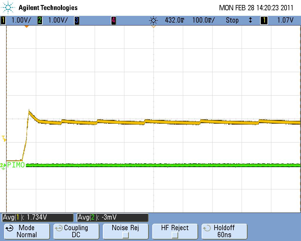
When I attach the main circuit, the charger output latches at just under 2V and oscillates a bit (see the scope shot attached). I disconnected some circuits on the main board and when I remove the connection to our GSM module, the charger will work. There are two 47uF ceramics on the GSM module that are connected directly to the battery.
I assume that the inrush current to these caps is too much and trips the “short circuit” protection in the charger – this is consistent with the charger datasheet that specs V(scind) around 1.8V. If I jiggle the charger input so it connects and disconnects quickly (before the battery discharges back to 0), then charging will actually start – so again I assume I’m just avoiding the major inrush and getting past the short circuit detection in the charger.
I can also get the circuit into a mode where the output of the charger is stuck at about 2.98V and no current flows into the battery – I assume this is the battery protection circuit (which is specced to come on around 3V) turning off so no current can charge the battery (this is about the V(lowv) spec of the charger).
I’m guess-and-testing some different values for the resistor between OUT and BAT to see if that makes a difference. Not yet.
I’m wondering if I could add a bit of resistance right at OUT on the charger to limit the rush current. Or even an inductor. I cannot afford any resistance from the battery to the main circuit, but from the charger to the battery would be okay. Since I charge at 500mA, I’m not sure if this would screw up the charge sequence – probably not as I think it would sense before the resistance and still fully charge the battery since CV mode is last so the drop on the R would reduce.
Any ideas?"