This thread has been locked.

If you have a related question, please click the "Ask a related question" button in the top right corner. The newly created question will be automatically linked to this question.

TPS2115A: Indicator LED for Supply in Use

Part Number: TPS2115A


Hi,

I am currently designing a board which requires the possibility of being supplied via the +5V Vbus of the USB, or an external +5V DC. We decided to utilize Power-ORing using the TPS2115ADR. In our setup, I need the current limit to be 2A full so I used Rlim=250 Ohms. I then used CL=1uF, RL= 100Ohms, Cin1 = Cin2 = 0.1uF. 

Also, I wanted to utilize the STAT pin to implement an LED indicator that will tell if the 5V output of the TPS2115A is the USB 5V or the External 5V. From the image below, I connected an arbitrary Rstat in series with a Dstat supplied by the 5V External VIN. From the truth table, Since D1 is tied to GND, and D0 left NC (pulled up by the internal VDD), the Output and STAT pin output will depend on which of the two inputs (external 5V, USB 5V) is higher. 

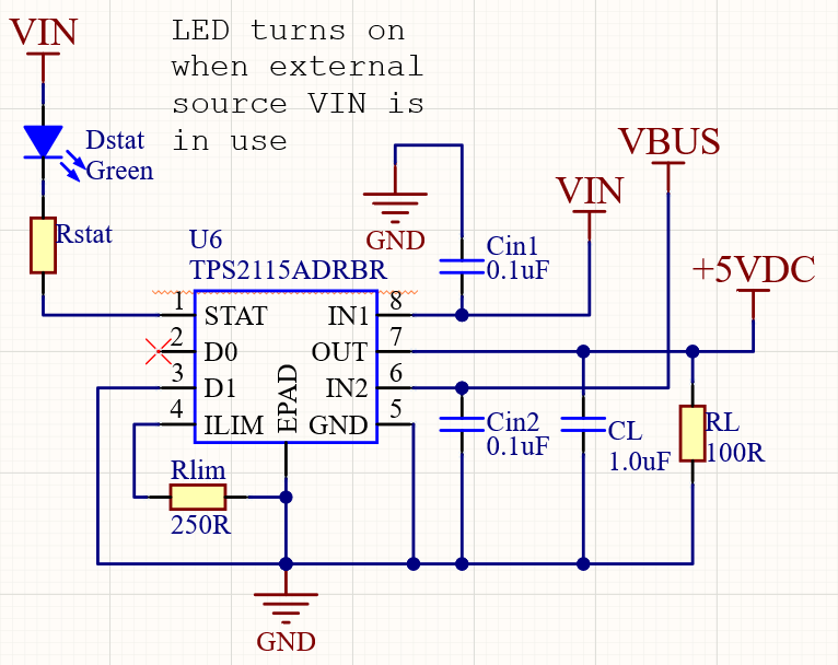
If I'm right, given the truth table, if the 5V output comes from VIN(Vin1), then STAT pin is pulled low and the LED will light up. However, if 5V actually comes from VBUS(Vin2), then STAT pin becomes Hi-Z and is pulled up to VIN and the LED won't light up.

Will that work? And in an instance that it would, what values would you recommend to use for Rstat(value) and Dstat(If, Vf)?
Other comments and recommendations about the setup will also be highly appreciated. Thank you.

  • Hi Ramon, 

    Your strategy for using STAT output to indicate which input is conducting is good. 

    However

    STAT isn't rated for high enough current to drive the majority of LEDs (5ma is ABS MAX) so it could only support a really really dim tiny led which may not be super useful. 

    Recommend to use STAT to control either PNP or NMOS as below, then you can drive a much bright LED, typically like 20mA+ depending on which. This will add virtually insiginificant cost to the design as well. 

    If this answers your question please let me know by pressing the green button. 

    Best

    Dimitri

  • Hi Dimitri,

    Thanks for the answer. I thought about it and based on your help, I was able to come up with this:

    I used an N-Channel MOSFET (Q1) with P/N: CSD17484F4T, to drive an LED (D1) P/N: SM0805UBWC with Vf=3.3V, If=20mA, in series with a 51 Ohm Resistor (R?). I also used a Pull-Up resistor of 10kOhms to the output 5V (+5VDC) of the TPS2115ADRB. 

    It works (I believe) this way:

    By default 5V USB (VBUS) is used and is connected to IN2 pin of the TPS2115ADRB. When external 5V (VIN) is connected, STAT could be Hi-Z or 0 depending on whichever is higher. If VIN is chosen as +5VDC, it means that STAT is 0 and so the LED would not light up. However, if VBUS is chosen as +5VDC, it means that STAT is Hi-Z and the LED should now light up.

    In regards to this, if my revision is now correct, can you please confirm if the values I used (Rlim, CL, RL, R?, D1 and Q1) are correct and should work properly?

    Many thanks to your help

    Ramon

  • Ramon, 

    Your component choice looks fine, ILED~33mA, but the Q1 FET is overspecced and unecessary, A larger gate charge has no benefits for this purpose. ~200mA rated FET, like common thru hole (to-92 type pkg) even is more than enough for this purpose!

    Please let me know if any other questions. 

    Best

    Dimitri