

Part Number: TPS92515
Hi Team,
Customer is using TPS92515 in there project, and find one issue.
Vin from battery, voltage is 22V, vout connect to 5 LED, voltage should be 17.8V during normal operation. measured average current ~0.76A.
The following firgure 1 is schematic. Inductor is 47uH, 1.45A saturation current.
Some board works normal, Boot voltage as figure 2 shows.
Some boards works abnormal, Boot voltage as figure 3 shows, output voltage as figure 4 shows.
Does it cause by drop-out mode? Could you help share some comments on this?
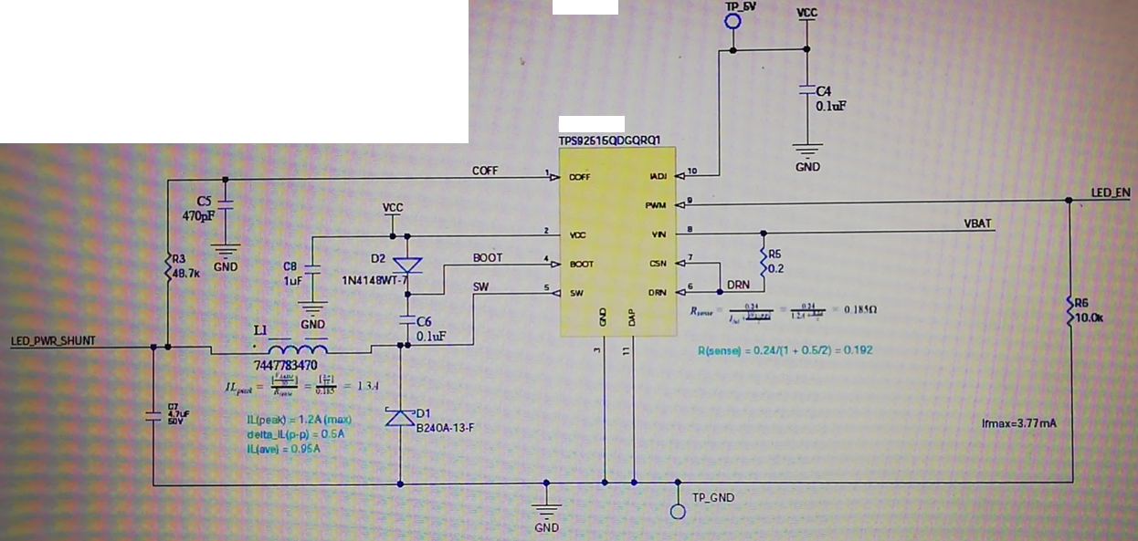
Figure 1

Figure 2
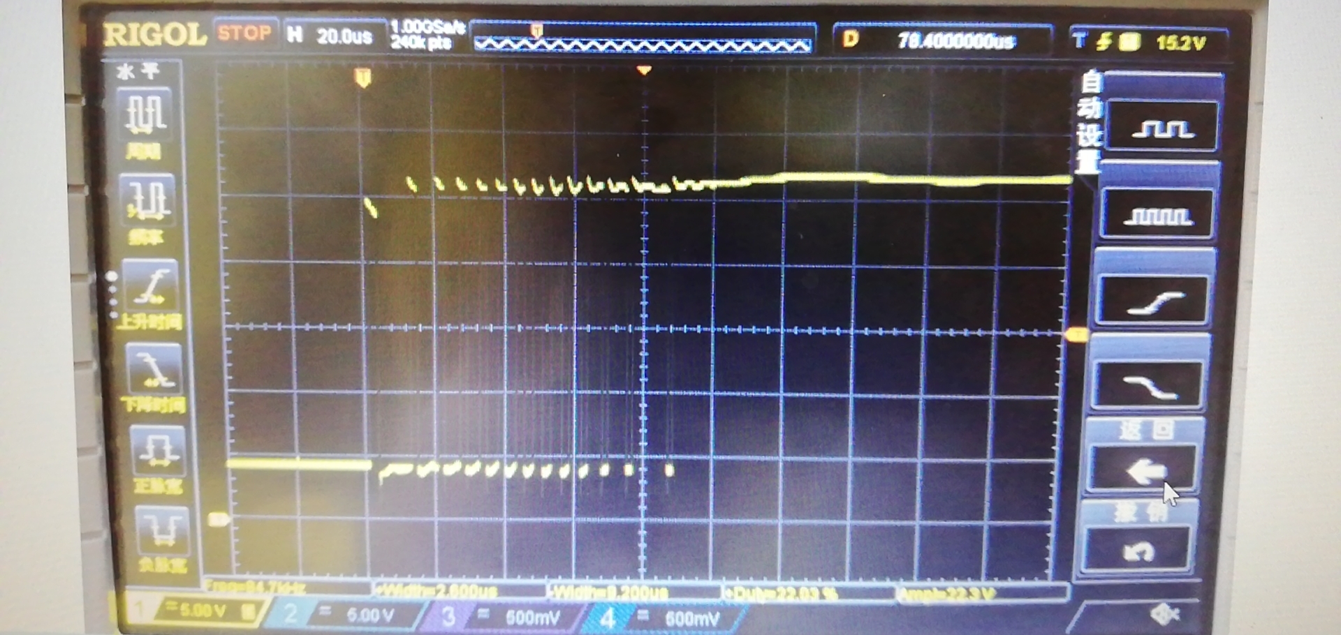
Figure 3
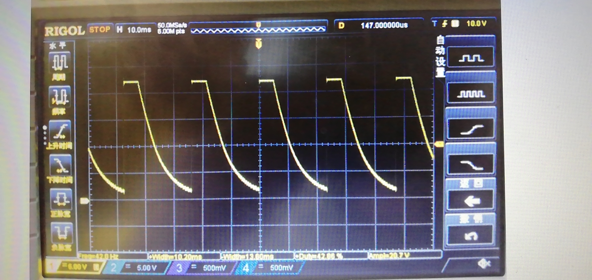
Figure 4
Thanks and Best Regards,
Will
