This thread has been locked.

If you have a related question, please click the "Ask a related question" button in the top right corner. The newly created question will be automatically linked to this question.

TPS61099EVM-768: Audible tones under certain load conditions.

Part Number: TPS61099EVM-768
Other Parts Discussed in Thread: TPS61099, TPS61071-Q1, TPS63900

Under some load conditions the TPS61099EVM-768 emits low level, audible tones.

I’d like to understand if others have observed this and how to minimize or prevent this on a design that uses the TPS61099.

The R1 and R2 resistors were changed out for R1=750 kOhm (RC0402FR-07750KL) and R2=249 kOhm (RC0402FR-07249KL) to change the output voltage to around 4.0 V.

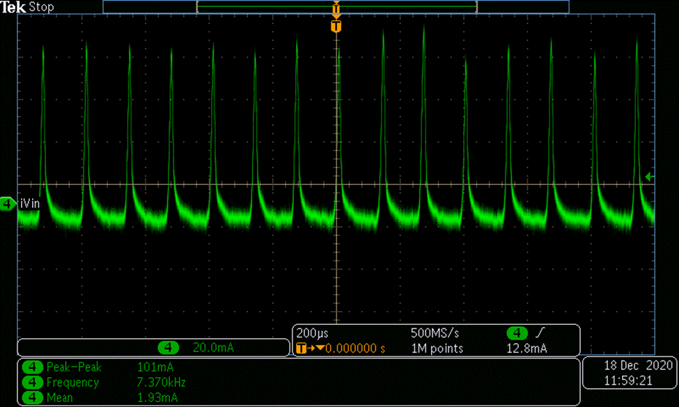
Under the load condition of VIN=1.8 V, VOUT=4.07 V, Load=1.1 kOhm, 3.7 mA an audible tone around 8 kHz emits from the board, when the TPS61099 is in the burst mode.

The Vin current waveform has a period of 0.128 ms or frequency of about 8 kHz, which is right about where the tone is at. I used a spectrum analyzer app on my phone that shows the 8 kHz tone that aligns with the current waveform frequency and thus I’m guessing the switching frequency of the inductor.

A Keithley 2460 SMU is used to power the eval board via 3ft test leads and loading Vout with a resistor box connected via 3 ft cables.

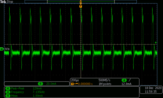
When a different power source is used, GWINSTEK GPD-3303S power supply the audible tone is reduced but still there. The current waveform from the Keithley 2460 is different from the GW INSTEK, so maybe that’s part of the reason why the tone amplitude is different.

The real product will be powered by two AA batteries in series, which hasn't been tested yet.

Here is the 8 kHz VIN current waveform capture that produces an audible tone when the Keithley 2460 is powering the board on the 1 A range and compliance.

A Tektronix TCP0030A current probe was used to make the measurement, it is placed around the negative VIN lead.

GW INSTEK GPO-3303S power supply, audio tone lower in amplitude.

Again, the main thing I want to know is how to prevent any audible tones when using the TPS61099 part in our design.

  • Hi Charlie,

    As you observed and introduced in datasheet, the device works in Burst mode at light load to get high efficiency, so the frequency will reduce. The audible tones are inevitable, so using metal alloy inductor will be better. If you do not mind low efficiency at light load, adding a resistor as dead load is another solution.

    Best Regards,

    Yichen Xu 

  • Yichen,

    I have the following questions/requests in order of priority:

    • Isn't the evaluation board already using a metal alloy inductor, part DFE252012P-2R2M=P2? I was planning on using the LQM2HPN2R2MG0L inductor in our design based on the recommendation of the WEBENCH for our use case, but it appears that it's a ferrite type inductor, so would likely have worse audio tone performance.
    • Can you provide and example 2.2 uH inductor part that would be less susceptible to producing audio tones?
    • What is the actual mechanism that causes the audio tone? Is the inductor vibrating, what is mechanically vibrating?
    • Can you suggest an alternative to the TPS61099 boost regulator that can operate in the continuous mode all time?
    • With Vin=1.8V to 3.8V and Vout=4.0 V, what is the current load needed to guarantee continuous mode and then what is the minimum load to keep the device in the continuous mode.

    As for your suggestion about keeping the regulator in the continuous mode all the time by adding enough load current to the output, this might work because once the device is in the continuous mode, then it will stay there under fairly like loads, there seems to big a rather large hysteresis in the switch to and from continuous mode. For example, I observed that at Vout=5.0 V and VIN=1.8 V a load current of 12 mA or greater is needed to get the device into the continuous mode. Then 0.2 mA or less is needed to get the device back into burst mode.

    If the device starts up in high current mode, >30 mA for example, and then switches to a lower current mode, >0.3 mA for example, then perhaps the regulator will stay in the continuous mode.

    If I can receive from TI or determine via testing the minimum load needed to guarantee the device goes to the continuous mode and then the minimum load current to keep it in the continuous mode for our use conditions of VIN=1.8V to 3.6V, Vout = 4.0 V, then I can determine if the device could remain in the continuous mode all the time while still meeting the battery life requirements.

    Thank you,

    Charlie

  • Hi Charlie,

    1. Compared to inductors with no fixed coil shown below, the metal alloy inductor has better performance. And we do not have samples because TI is not a inductor supplier. 

    2. The magnetizing process itself will bring inductor vibrating, and the coil will also vibrate for above inductor. 

    3. The hysteresis for burst and PWM mode is normal. And the transition point is not constant with different loads. So you may need a larger dead load to avoid burst mode for the whole load range.

    4. If you really need no noise, a forced PWM device should be selected. What is the working condition you need? I can give you some recommended devices with forced PWM mode. Note the efficiency at load will decrease.

    Best Regards,

    Yichen 

  • Hi Charlie,

    Here is a better explanation about the reason of buzzing:

    https://www.coilcraft.com/en-us/faq/


    Best Regards,

    Yichen 

  • Yichen,

    For the first revision of our design, I am going to use the same inductor as on the TPS61099 evaluation board, DFE252012P-2R2M=P2, as it is a metal alloy inductor and is supposed to have lower audible noise than ferrite. 

    I was considering a larger inductor like FDSD0420D-2R2M=P3 (4.2 mm x 4.2 mm), a TDK app note suggested that a smaller inductor might have better performance because the natural vibration frequency would be higher :https://product.tdk.com/info/en/products/inductor/inductor/smd/technote/solution/acoustic-noise/index_mytdk.html/ It seems like the larger inductor would have more mass to help reduce vibration, but the natural vibration frequency would also be lower in frequency.

    For our use case the TPS61099 will be sourced by two AA batteries in series, so VIN=1.8 V to 3.6 V. The output is set to approximately 4.0 V. Average load currents will range from 0.2 mA to around 5 mA. For the average user the average current should be less than 1 mA. The peak currents might be fairly high, peak average current over many seconds of 50-70 mA and peak currents less than 1 ms in duration of up to 200 mA. There are few asynchronous peak currents from various components of the system that could all lineup on each other.

    The two AA batteries should last 10-14 days without replacement. The product is a trialing medical device where a patient is given a fresh set of batteries for a 10-14 day trial period to see if the device provide medical benefit to them. The batteries don't need to really last more than this 10-14 day trial period, so extremely low idle current might not really be necessary.

    I don't think the regulator will actually see 200 mA with sufficient capacitance in the system, but that is one thing that I liked about the TPS61099 is that it should have enough sourcing capabilities for our most extreme use case.

    I considered TPS61071-Q1 for our design originally that appears to have a constant PWM mode, but didn't go with it due to the higher static current and lower maximum output current than the TPS61099. 

    Please let me know if you have other constant PWM regulators that might be better suited for our application. 

    Charlie

  • Hi Charlie,

    1. For replacing inductor, you can also consider XGL4020-222 with a 4mm*4mm size。

    2. There is conflict in your requirement. Low light load power consumption and FPWM(forced PWM) mode can not be acquired at the same time. Because if you want no noise at low frequency, FPWM is needed; but FPWM will bring large current consumption at even no load(hundreds of uA or mA level), which make low static current meaningless. Note that no load current is not static current.

    3. It depends on the priority of your consideration. I would suggest that replacing inductor for a try at first, if the noise is still unacceptable, you may need other devices. TPS63900, a buckboost converter with only 75nA Iq should fit your requirement. It will still reduce frequency at light load but I never heard any noise. 

    Best Regards,

    Yichen

  • Yichen,

    For the first revision of the design, the smaller inductor will be populated and tested. If there are issues with audible noise then the larger 4.2 mm x 4.2 mm inductor will be tried. If audible noise is still present then we'll look at using the TPS63900 or a forced PWM mode part like TPS61071-Q1. 

    I understand that the downside of the forced PWM mode will be a large increase in light load static current, but this may be acceptable for the way the product will be used.

    I will close this issue.

    Thank you,

    Charlie