This thread has been locked.

If you have a related question, please click the "Ask a related question" button in the top right corner. The newly created question will be automatically linked to this question.

BQ77915: BMS is turned off when the pack is charged or discharged

Part Number: BQ77915

Hi,

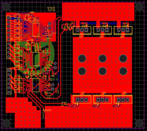
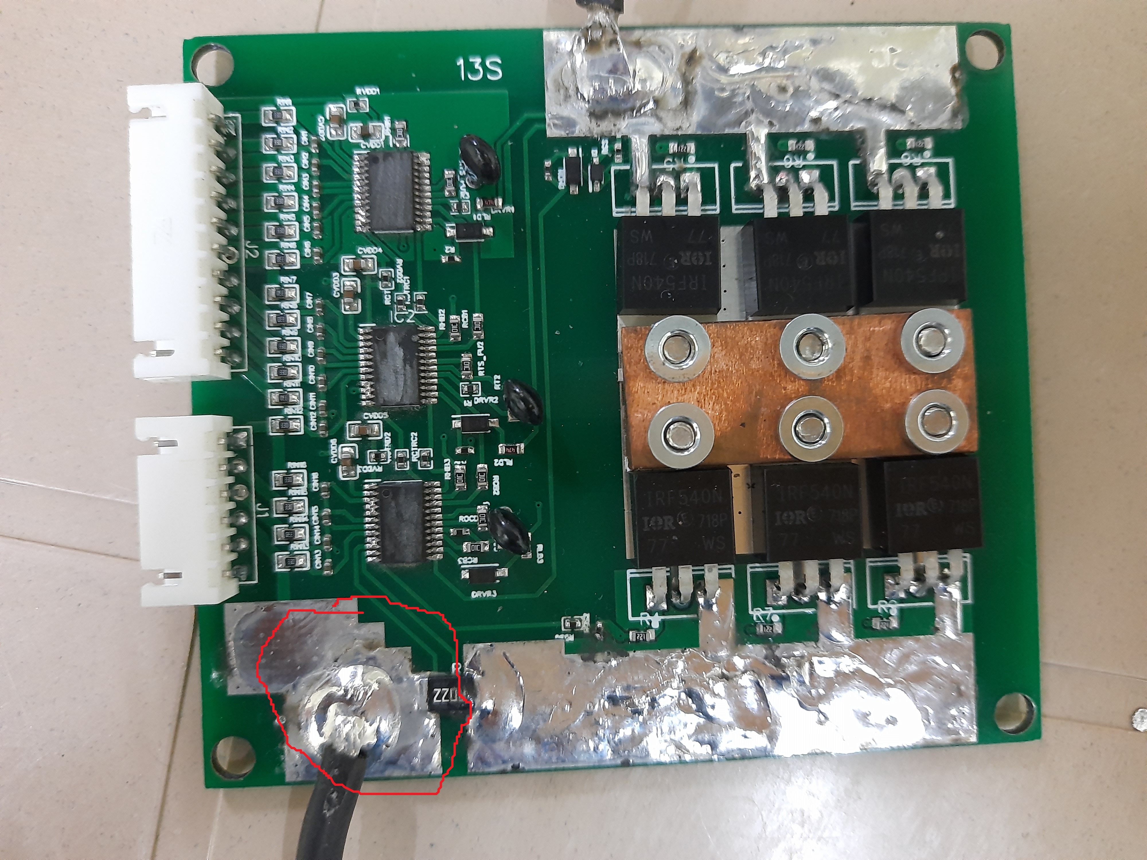
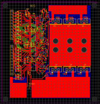
I have designed 13s Bms using three  bq791500 devices.  Finally I tested the Mosfet gate voltages  which is around 9.5V but when the pack is loaded ( either connected to charger or discharged), Bms is turned off automatically.

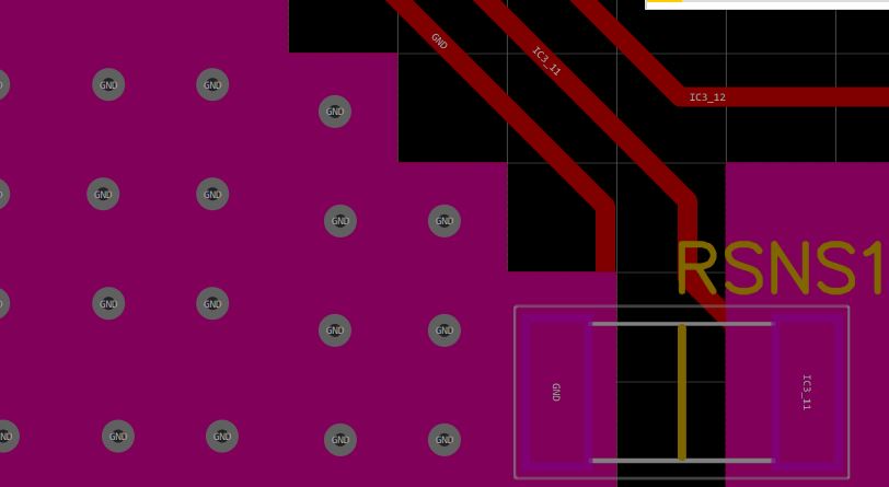
1. I used 2.5milli ohm current sense resistor , all charging and discharging are under limits of 6 amps..I previously designed 10s BMS ( i used same 2.5 milli ohms without any filters), which is working well.  Could you please guide me what would  be the possible problem , 

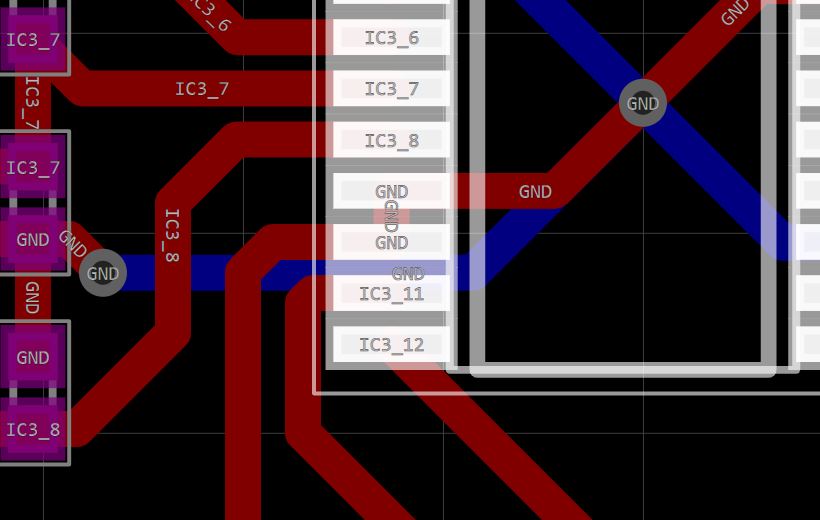
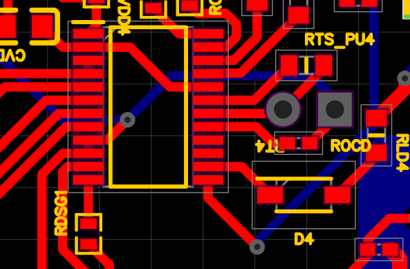
》 I used 6 IRF540 Mosfets ( 3 dsg mosfets 3 chg Mosfets ), Is this the one that is creating issue? but i could see the gate voltages of 9.5V on all 6 MOSFETS. Should I change any gate resistors? Please have a look  at my schematic and PCB design

  • Hi Mounish,

    The schematic clip does not show the GND connection on battery-, normally that is near the left side of the sense resistor.  I don't immediately see it in the layout either, but they can be very subtle.  There should not be anything special about 13 cells vs 10 cells from the successful system you mention, you may look for some ground shift specific to this board.

  • Hi,

    Left side of sense resistor is connected to B- ,Please look at the picture below ( rounded with red ).  What do you mean by " You may look for some ground shift" ? 

    Does using Multiple FETs like this is the problem? 

  • Hi Mounish,

    I see the B- connection to the board at the sense resistor, and to the sense resistor above, and to the J1 pin.  I can't tell how it connects to VSS.  It looks like the BQ77915 at the bottom has pin 9 connected to pin 20, but I can't tell if there is a via or path to GND/B-.  In the picture it looks like there may be a bridge between 9 & 10. If there is an open when you connect current the may be an abs max violation and the part may shut down.  

    Also check the PRES signal, make sure it is still high after the connection, CTRC, CTRD.  You can look at AVDD as well to see if it remains on.  

    The bottom part should function just like the bottom part of a 10S.  With fewer cells you will have lower voltages, but you might make comparative measurements between the 2 systems.

  • Hi,

    Pin 20 is not connected to ground and this is a 3 cell configuration, I hope this is the real problem

  • Hi

    I have another design 16S, each device uses 4 cells. So pin 20 is connected to AVDD as shown below. I have shorted VSS and SRP pins to ground. Is this the one that is creating issue. i,e., When I connect a 6amp charger or try to discharge the pack@15amps, BMS is turned off.. Please help

  • Hi..please help me with above question

  • Hi Mounish,

    Connecting CCFG to AVDD is the proper configuration for 4 cells.

    If the system shuts down from current flow, the following seem they might be issues:

    • Shift in GND for the device.
    • Collapse in voltage due to load.  Should not happen with charge though.
    • OCD/OCC detection and protection.

    It is likely that a careful check of the state of each part is needed after the event and to compare to before the event.