Hi Team,
My customer is using p2p solution TPS54620/RT2856. Currently when they are having 6.2Vin/5Vo, 600kHz and RT2856's maximum duty cycle cannot meet requirement. So they have proposed below scheme to increase duty cycle. From my point of view, Vou and internal Boot charge has formed a simple OR-ing circuitry, which will charges Cboot when BOOT charge capability is low. I have below questions. Could you please give your comments accordingly? Thank you very much!
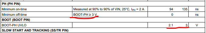
1.The maximum Duty cycle is 1-Fsw,min*Toff,min. I checked datasheet the minimum Toff is 0ns, so this mean TPS54620 can work in 100% duty cycle. Please confirm;
2.Is that ok to add a diode here even though it does not work for TPS54620? Customer wants to have bom to bom so if we are ok to add diode it will be good.
3.What is other risk point here?
-Wenhao