This thread has been locked.

If you have a related question, please click the "Ask a related question" button in the top right corner. The newly created question will be automatically linked to this question.

WEBENCH® Tools/UCC2808A-2: Push-Pull: Issues with MOSFET's gates

Part Number: UCC2808A-2
Other Parts Discussed in Thread: UCC28704, , TPS2812, TL431

Tool/software: WEBENCH® Design Tools

Hello Dear Support!

I am trying to build circuit generated in WEBENCH Power Designer. The trouble is - signals going to MOSFETs gates are really far from PWM shape. Something is wrong on MOSFET paths, because when i plug out the gates from device - PWM signal is correct. Link to project and signals pictures below.

Thanks for answer!

Direct link to project: 

https://webench.ti.com/power-designer/switching-regulator/customize/8

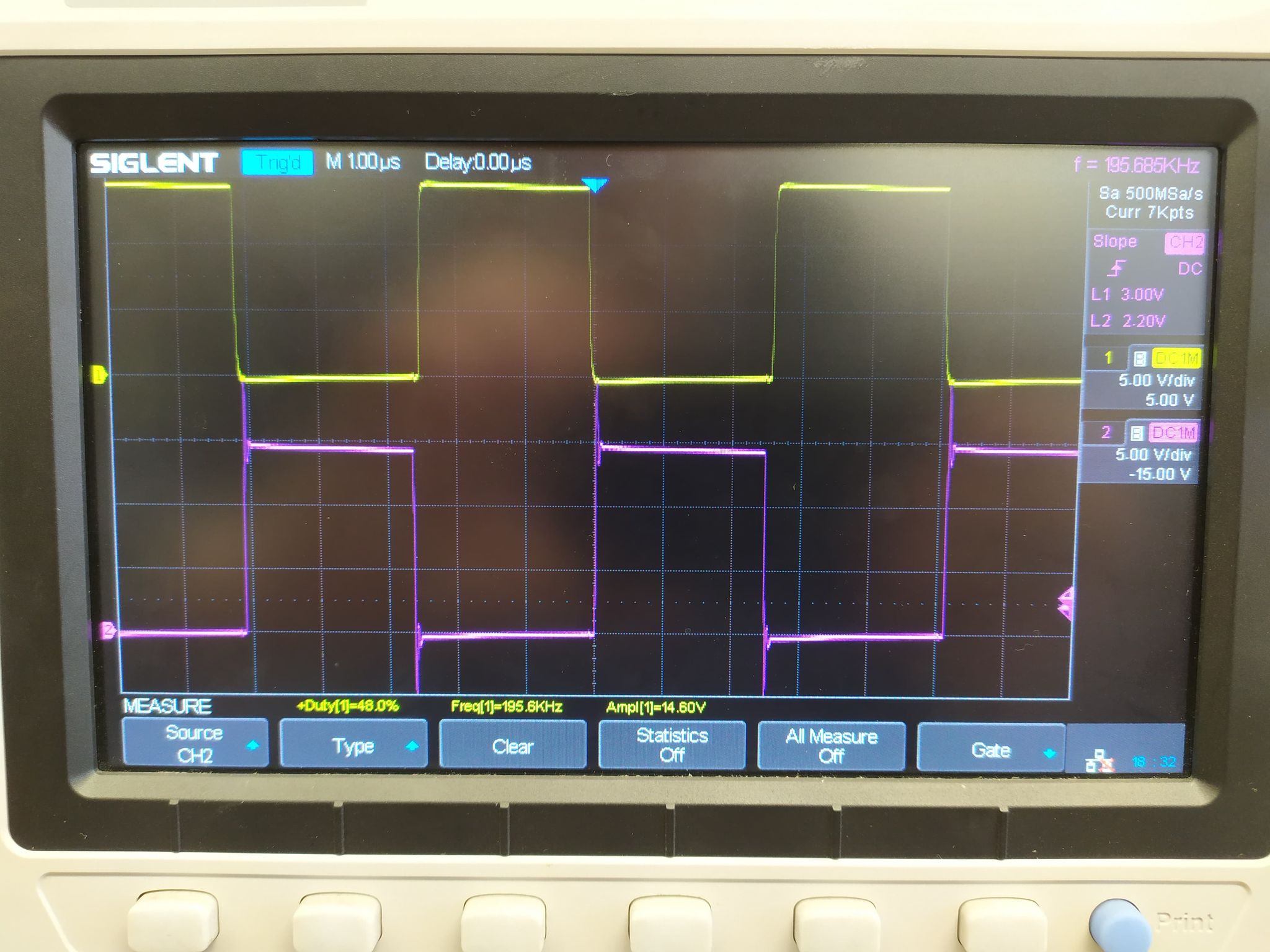
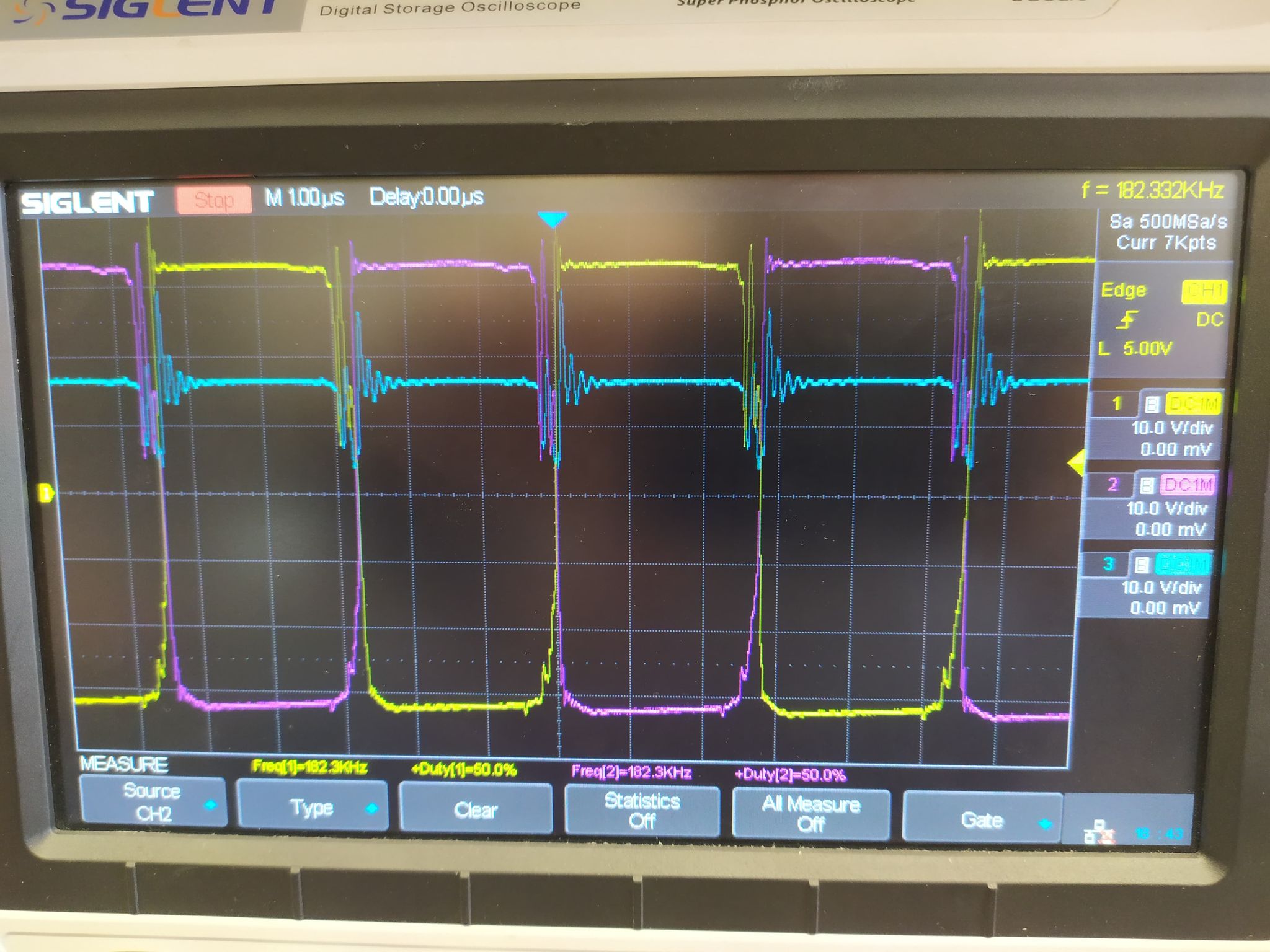
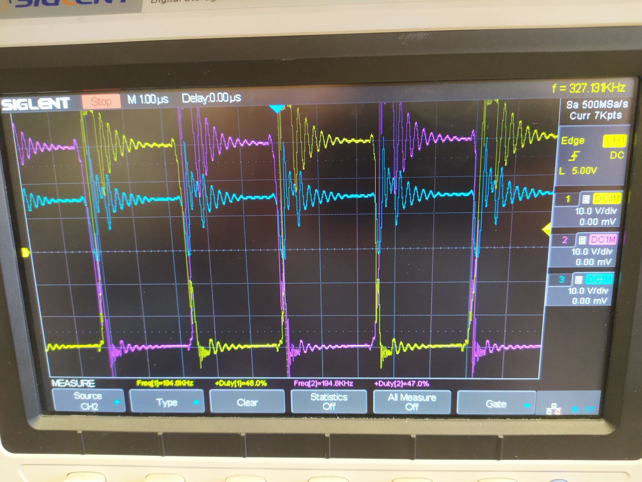
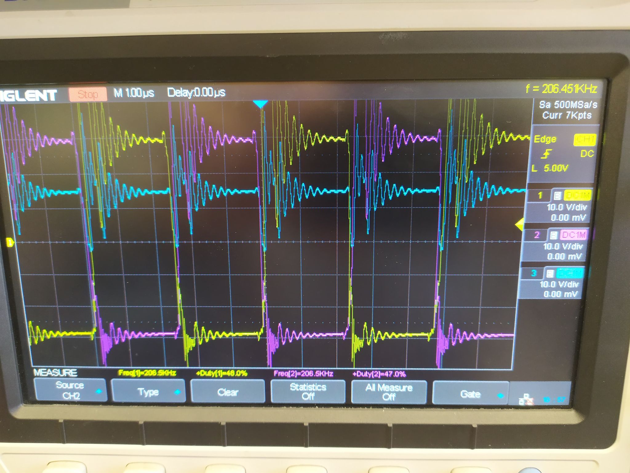
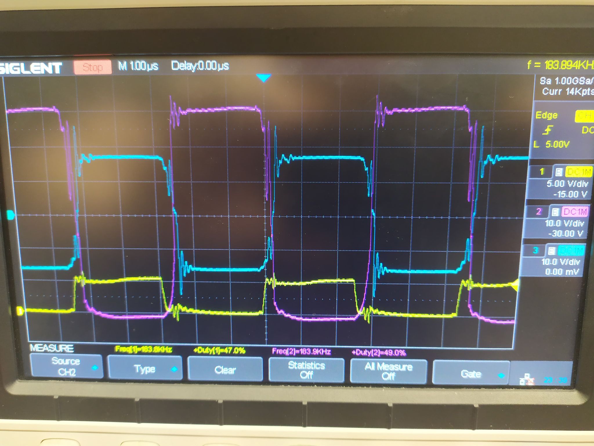
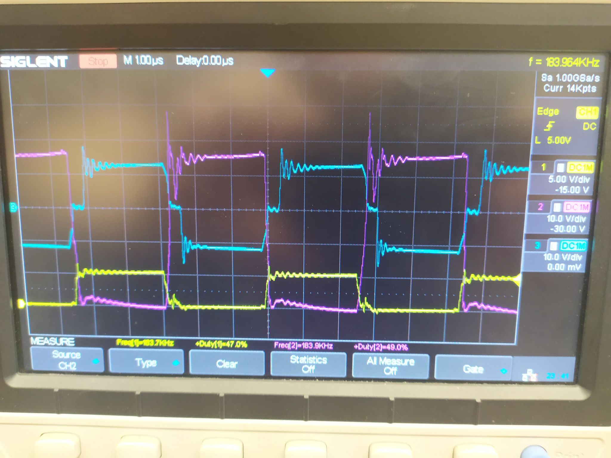
Signals with connected gates:

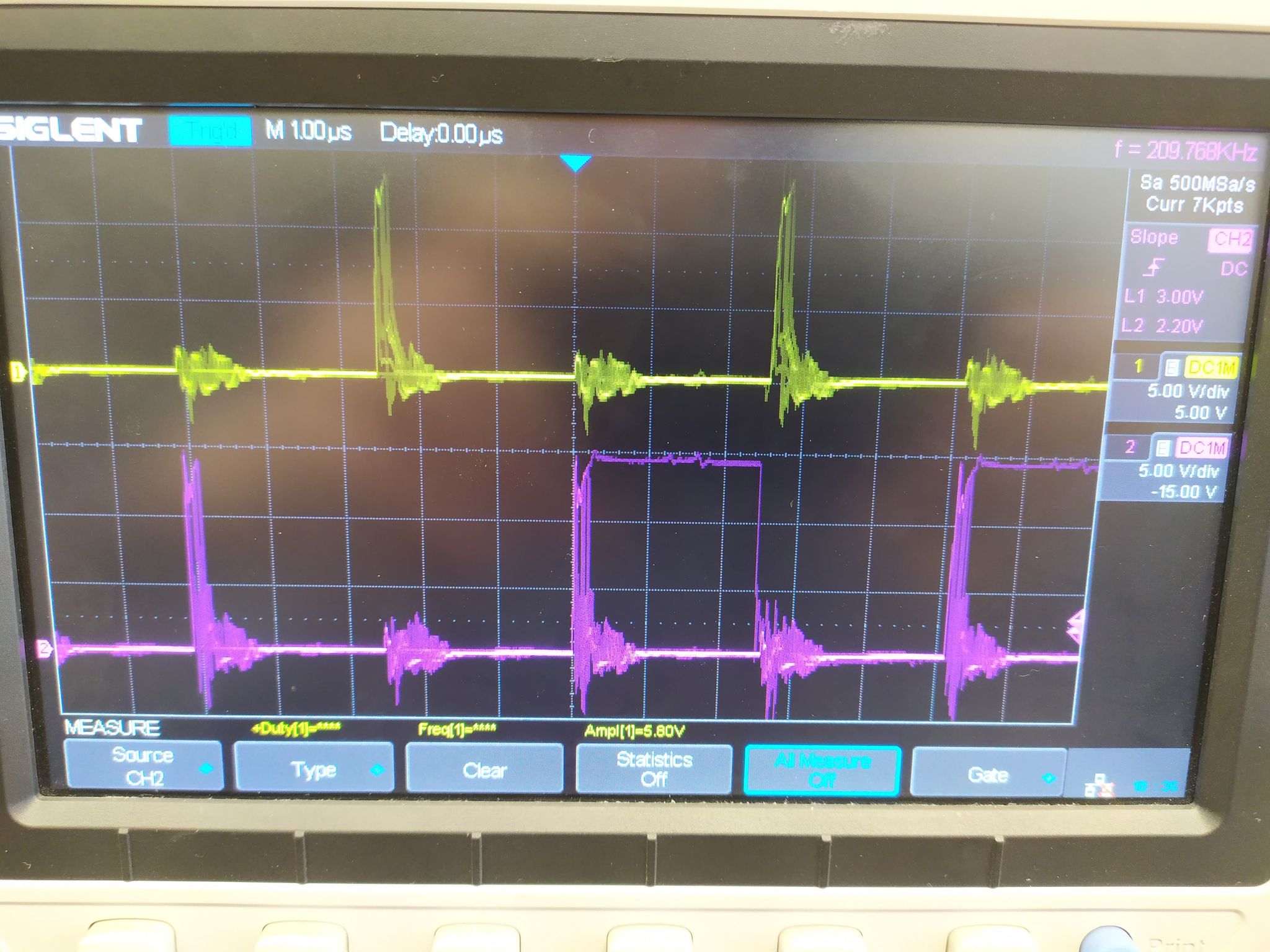
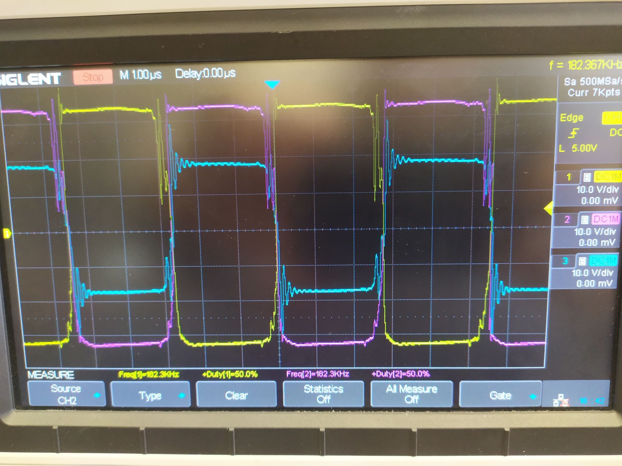
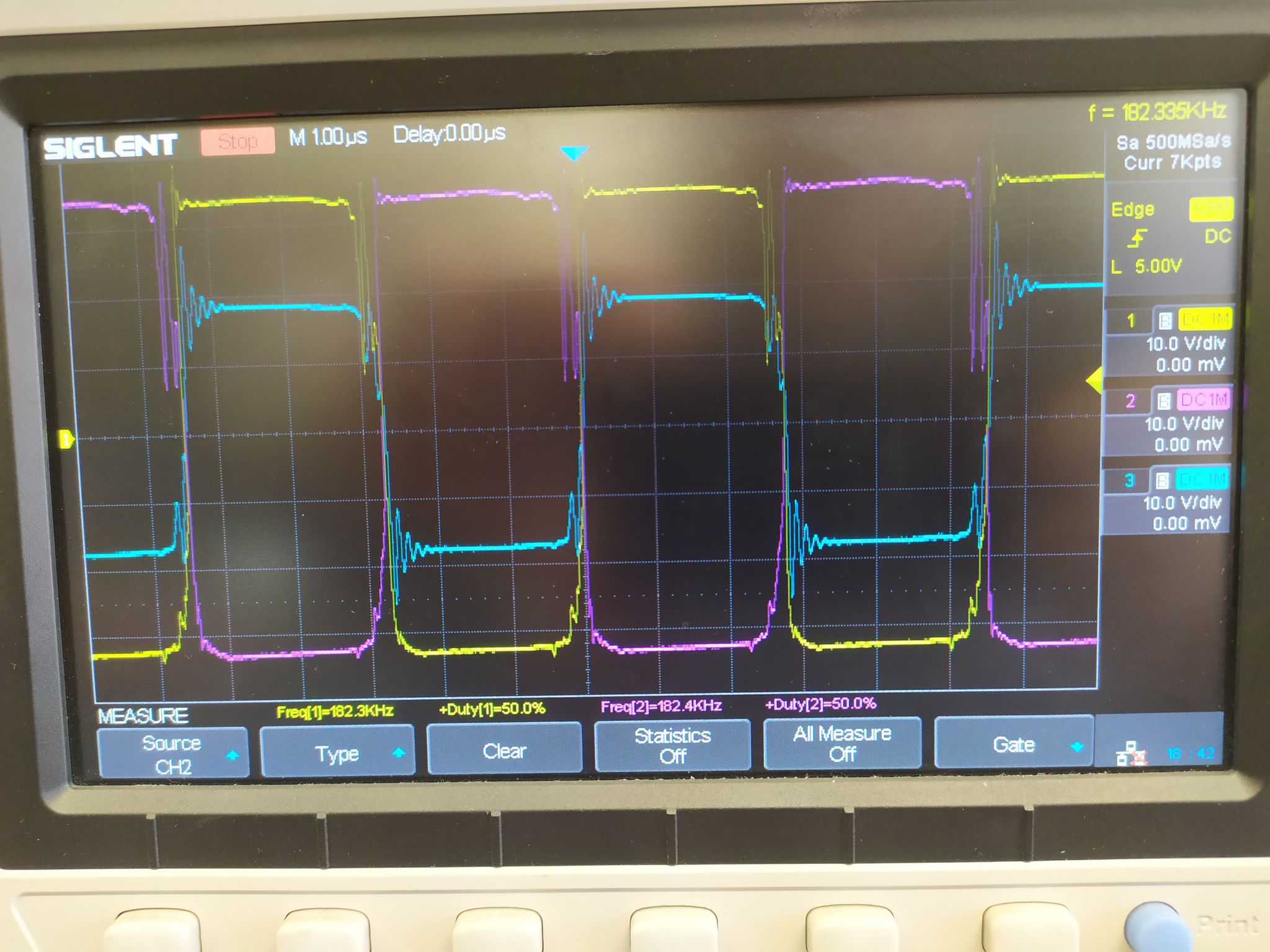
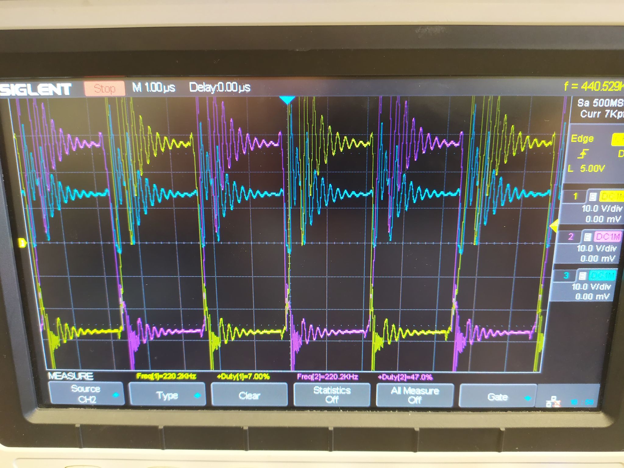
Signal with disconnected gates:

  • Hi, Oskar

    Thanks for your interest in TI here. I will be happy to route your request into the appropriate team to support. Please note the team that supports this device is in the US so they will have a delayed response due to the US holiday. Please expect a response in the week of Jan 4th.

    Yunsheng

  • Hi, Yunsheng

    Of course I understand the situation, thanks for answer before Europe's holidays as well! Merry Christmas to the whole team!

    Oskar

  • Oskar,

    Merry Christmas to you too.

    Yunsheng

  • Hi,

    Your link to webench is actually showing UCC28704. Please check the link you provided. If it is UCC28704, please change your thread title as UCC28704 is to be supported from a different group.

    If it is UCC2808A, please correct your link to be for UC2808 as it is now UCC28704.

  • Hi Hong Huang,

    Hmmm, I checked the link and on my computer it's redirecting me to my scheme with UCC2808AD-2D. I will try to rewrite the link, if it wont work anyway, I will write parameters, that I used to generate scheme.

    It is definitely UCC2808A-2. 

    Thank you for getting intrested in my problem before New Year Holiday!

    EDIT: New link: https://webench.ti.com/power-designer/switching-regulator/customize/11?noparams=0

    In case of problems, here are the necessary parameters: 

    DC-DC Converter -> 14-50 Vin -> 24V 10A output -> isolated output.

  • Hi,

    Your link still shows UCC28704 - see the below from your link screen shot? Can you make a screen shot instead of the link to attach to  your message? I need to see your circuit to understand the issue so your detail does not help to understand your issue.

  • Hi,

    The problem is that WEBENCH generate schematic with terrible components management so I have to zoom in almost every component near the ICs. This is the last time Im trying with link to my project - if this one wont work I will draw fixed schematic by my own.

    Thanks for answer!

    LINK: webench.ti.com/.../SDP.cgi

  • Hi,

    When you say disconnect from gate, can you specifically indicate how do your disconnect - disconnect from TPS2812 from UC2808, or disconnect TPS2812 from MOSFETs?

  • I am disconnecting MOSFETs from TPS2812. Resistors 3R and 10k are still connected - I am unsoldering the gates pins. 

    EDIT: It is problem with the transformer. When only one winding is connected, circuit is behaving like it should work fine, but when i plug in whole primary winding - signals are just like the pictures i showed in first post, and whole transformer is *buzzing*

  • Hi,

    You may check your transformer winding polarities. Also, you may disconnect your secondary-side diodes to see how your converter behaves. It looks like your transformer polarities are not properly arranged.

  • Hi,

    I checked the windings and polarities are fine. I have also checked both primary windings by connecting only one of them and the secondary-side looks the same, moreover nothing is changing whether the secondary-side is connected or not. When I am waiting with transformer connected and buzzing for like 20-30sec - current rises to above 2A and TPS2812 is burning. 

     I wonder if I properly understand WEBENCH notification about transformer. 

  • Hi,

    How is your transformer connected ? Is it with correct polarities? How is your power stage ? Is it ok?

    Your check shows the issue is due to your external circuit not the IC so you need to check your circuit to find out.

  • Hi,

    You need to check your transformer polarities by measurement each waveform to make sure they are correct. Check on paper may not help to confirm your connection correct as your transformer polarities may be different from your circuit symbol on paper.

  • Hi,

    Sorry for sooo late response. I think my transformer is fine - pictures below shows osciliscope signals on primary and secondary side. Last picture shows the voltage after D4 and D5 schottkys.

    With unplugged load - Vout is 22,5 V but when I try to load the circuit - it drops instantly to 17,5 V with 100 mA.

    The second issue I noticed is that I'm using 31 Vin which should produce 40% duty cycle, while mine DC is 50%. 

    My supply voltage for UCC2808A is 6 V and it supply also optocoupler O1 and Q1's emitter. When I'm increasing Vcc i get more ringing in signals, wich is also on the pictures. 

    Yellow signal is voltage on primary winding connected to MOSFET M1

    Purple signal is voltage on primary winding connected to MOSFET M2

    PICTURE 1: BLUE SIGNAL - VOLTAGE ON UPPER SECONDARY WINDING

    PICTURE 2: BLUE SIGNAL - VOLTAGE ON LOWER SECONDARY WINDING

    PICTURE 3: BLUE SIGNAL - VOLTAGE AFTER D3 AND D4 SCHOTTKY


  • ISSUES WITH VCC


    6V Vcc:

    7 V Vcc:

    8 V Vcc:

    9 V Vcc:

    10 V Vcc:

    Is it possible that higher frequency (220kHz for 10 V) is too high for designed circuit?

  • Hi,

    Can you capture your MOSFETs waveform and your transformer secondary-side winding waveform when you load your converter? The voltage drop when you load your converter should be from your converter not deliver enough energy which is achieved by voltage and current on the transformer. So check your MOSFET and transformer will help to find the issue. If the duty cycle is full, then your converter cannot regulate output. So you need to capture the mentioned waveforms mentioned go from there.

    On the second issue, the debugging is similar, you need to check if your output voltage is in regulation. If not, check the duty cycle and feedback loop to see each portion circuit works ok or not.

  • Hi,

    By "MOSFET's waveform" you mean signal on gate or drain? 

  • Hi,

    Vds, drain to source.

  • Yellow signal - Vgs

    Purple signal - Vds

    Blue signal - secondary winding

    Picture 1: loaded only by multimeter

    Picture 2: 1A Load

    Picture 3: 2A Load

  • Hi,

    So you have 1A and 2A, load, what is your output voltage, is the output voltage correct?

    What is your input voltage for the 1A and 2A load? What is your problem with the waveform you show? It looks ok to me.

  • My output voltage with only multimeter connected is +/- 13,3 V, for 1A it's 10,2 V, for 2A it's 7,5 V. 

    I know my waveforms looks correct now, but I cant figure why we can see those voltage drops. It is because circuit isn't in regulation and it's not reacting for changing load? How can i measure feedback loop? On secondary side there are 3 resistors and TL431 - should i try using external supply to generate 2,5V on Rfbb and measure Vce on optocoupler?

  • Hi,

    Your waveform shows the duty cycle is full. I think that is why your output voltage drops. What is your input voltage? You can increase your input voltage to see if your output voltage increases or not. If yes, that means, your transformer turns ratio is not correct.

  • I had 31 VDC input voltage and just checked it. Yes - the voltage increases when I increase Vin, but it was going up to 35 V on output without changing duty cycle. Will it be proper when i change the tranformer? I'm worrier that duty cycle didnt change at all when output voltage was at 24 V and higher.

  • Hi,

    Your waveform shows full duty cycle, and increase input voltage makes increase output. All these means your transformer turns ratios are not correct. You need to correct your transformer turns ratios before other debugging.

  • Hi,

    Could you please guide me how it must be done?

    Here is Ns1 and Ns2 in comparision to Np, while I have 2 primary windings. It means Ns1/Np1 = 1.905 and Ns2/Np2 = 1.905 or secondray windings turns must be in proper ratio to whole primary winding?