Hello,
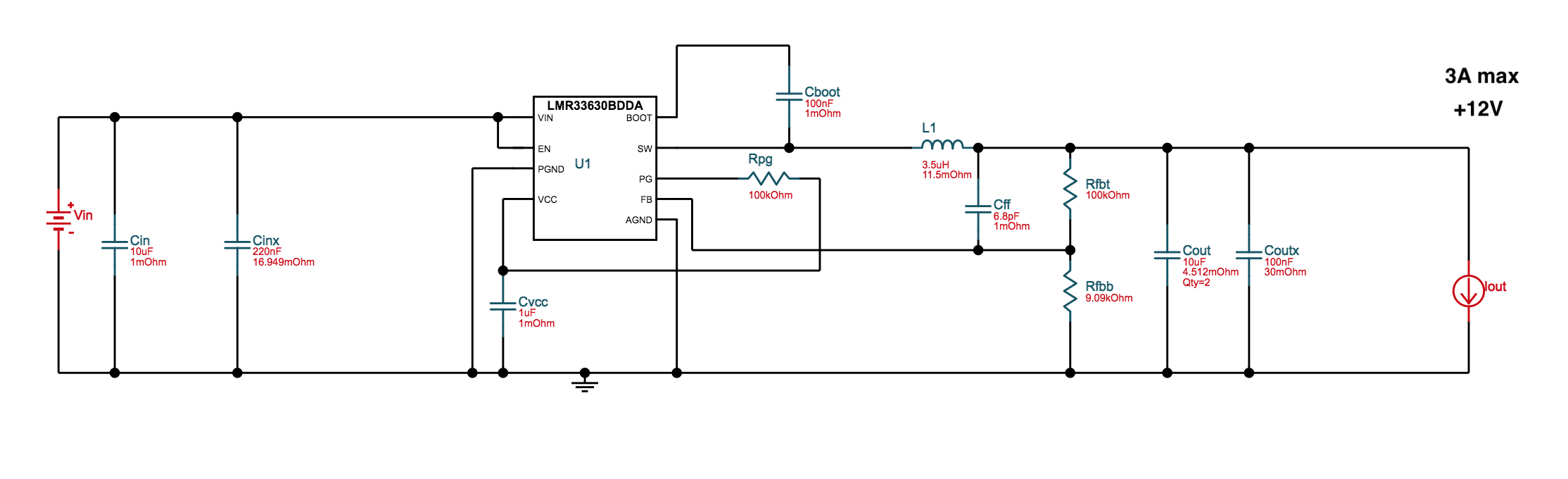
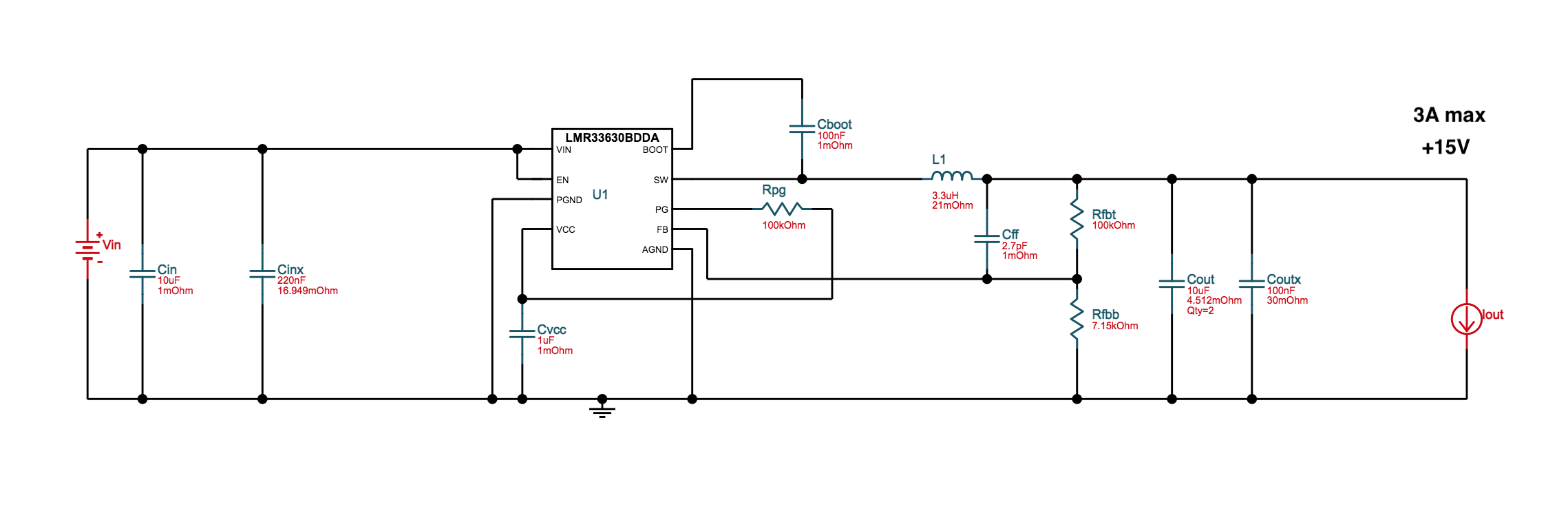
Below is a rail design for inputting +18-22V DC and outputting +12V DC, and a nearly identical design for outputting +15V DC.
There is a resistor "Rfbb" and a capacitor "Cff" with significantly different values, and an inductor with a small difference in value.
I'm considering installing a pcb DIP switch to have the resistor and capacitor changed to different values so as to be able to flip a switch to choose between 12 and 15 output voltage. The current would of course flow through the switch terminals.
My question is... how much current is flowing through that resistor and cap whenever the load is drawing a lot of current? Would it be safe to use a small DIP switch inline with those points? Or would i need to use heavier duty switches that can handle a full 3A?
I would guess that the resistor's pathway is pretty low current activity since there's a 100K resistor before it, but am unsure about the current flowing through the capacitor Cff.
Any advice would be appreciated, thanks!
As for the inductor, i might be able to select a tighter tolerance inductor and have the value be split between the two designed values so that it's always in range of both.