Hi Team
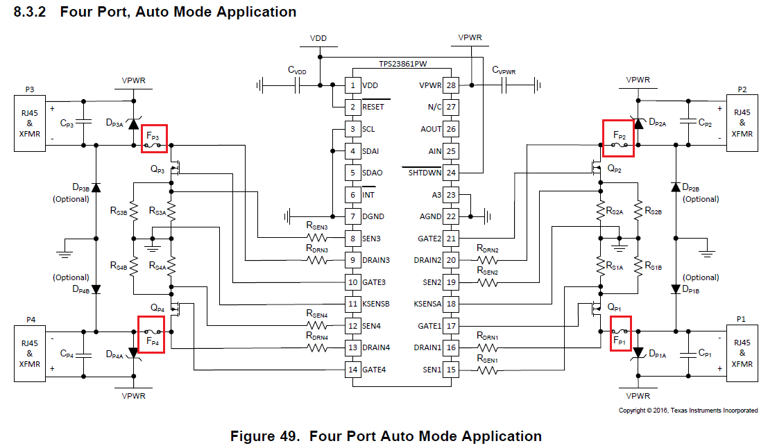
I'm planning to design the schematic following Figure. 49 in the datasheet, but I don't want to reserve the fuses.
How should I set the overcurrent condition if I2C connected to the ground as like Figure 49?
Hi Team
I'm planning to design the schematic following Figure. 49 in the datasheet, but I don't want to reserve the fuses.
How should I set the overcurrent condition if I2C connected to the ground as like Figure 49?