Other Parts Discussed in Thread: BQSTUDIO, EV2400,
Dear Team,
I'm working with the BQ25895EVM-464 board and the EV2400 interface board (firmware v. 0.18), BQSTUDIO v1.3.101 on a Win10 64 bit machine.
Communication with the evaluation board seems ok but I can not understand why the parameters on the registry is changed when the /CE pin is switched.
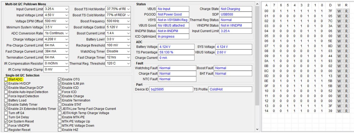
Actually I'm working with a little LiPo battery (420 mAh but able to give in discharge up to 15C) so I've set a fast charging current equal to 384 mA (REG04), precharge current and end-charge current are set to 64 mA (REG05), the minimum settings available inside BQSTUDIO and from BQ25895 datasheet.
The Input Current Limit is set by the registry to 3.25A (REG00) and the R19 trimmer on the evaluation board was tuned to achieve 0 ohm, so the only effective resistace on the ILIM pin is given practically only by R1=130R so the value of the maximum input current set by the limiting resistor is equal to IINMAX=390/130=3 A (suppose KLIM_max=390).
The idea is keep the /CE pin high, write the parameters on the board and the force a low level on the /CE pin to enable the charging of the battery avoiding then a too high charging current that is set from the default register value...
But when I perform the registry write and then I manually read back the registers content the value seems not updated and equal to the default values though the Device ACK into the BQSTUDIO is OK hence I think there are no communication errors with the device (the EV2400 I2C Clock Speed is set to Low Speed 100 kHz).
I've attached my registry settings for your reference.
Thanks and best regards.
F.
Register settings
* Created: Mon Dec 28 14:28:13 CET 2020
*
* Format: Register Name  tab Character,\t  Hexadecimal register value.
* Device: bq25890
* BQZ Container: Charger_1_00-bq25890_895.bqz
*
Input Current Limit, HIZ and ILIM pin	7F
OTG Temperature thresholds, and Input Voltage DPM Offset	05
ADC controls, OTG Frequency, ICO, DCP, and Input Detection	7D
Battery Load, WDT Reset periods, OTG and Charge Enable, and MINSYS setting	3A
Fast Charge Current Limit settings and MTK Pump enable	06
Pre-charge and Termination Current Limit settings	00
Charge Voltage Regulation Limit, Battery Low Voltage and Recharge threshold	5E
Termination Current Enable, STAT pin, WDT, Safety Timer, and JEITA Charge Current	8D
IR Compensation and Thermal Regulation thresholds	03
ICO, Extended Safety Timer, BATFET control, MTK Pump Voltage, and JEITA Charge Voltage	44
OTG Regulation Voltage and Current Limit settings	93
Charger VBUS, Charging Mode, PG, USB Input, and System Voltage Regulation status	A6
WDT, OTG/VBUS OVP, Thermal Shutdown, Safety Timer, and TS pin faults	80
Input Voltage DPM settings	13
Thermal Regulation Charge Status, and ADC Battery Voltage conversion	5C
ADC System Voltage conversion	5F
ADC TS pin voltage as percentage of REGN conversion	52
VBUS status, and ADC VBUS Voltage conversion	98
ADC Charge Current conversion	00
DPM status, and Input Current Limit setting	3F
Registers reset, Input Current Optimizer status, Device ID, and Temperature Profile	39


