This thread has been locked.

If you have a related question, please click the "Ask a related question" button in the top right corner. The newly created question will be automatically linked to this question.

BQ24075: bq24075

Part Number: BQ24075

Hi,

EN1 -0V ,EN2 -5V,TS - 0.6V,-ILIM 1K i had only 1K instead of 1.1K in my stock, R-ISET 866 ohms.

I wanted to charge my battery at 1A because i am using 2500mah,3.7V and i want to charge my battery in 2.5 hrs only.

Input is supplied from DC power supply Input voltage :5V

My problem is current consumed from DC power supply is never exceeding 0.2A,With this current battery took almost 6 hrs.  to charge from 3V to 3.8V(which is not even full capacity of battery).How to set the fast charge current to 1A, So that my battery will charge in 2.5hrs considering no Efficiency loss.

I have changed R_ISET to 590 ohms and current consumption increased to 0.3 - 0.4A sometimes going to 0.55A,But having ISET resistor 590 Ohm, battery has to charge at 1.5A, But it is not.

If the input voltage supplied is 5.9V current consumption increased from 0.2 to 1A. but the PCB is getting heated up.

Am I doing anything wrong?

Please Help.

I was not happy with response in previous thread and i am opening a new one and hoping for a solution. Link to my previous thread please go through it once  : e2e.ti.com/.../3570572

Thanks & regards,

P.Akhil

  • Hi,

    Here is my design.

    Thanks & regards,

    P.Akhil

    6180.TI.pdf

  • Hi P.Akhil,

    I apologize for the delay, I've noted the schematic in the previous thread and as it is the same issue, we will continue support over there. 

    Link: https://e2e.ti.com/support/power-management/f/196/p/966286/3574926#3574926

    I am closing this thread and marking as resolve to continue over there. 

  • Hi Akhil,

    I was able to review both the threads. I don't see any concern with the schematic. 

     My first suspect would have been thermal regulation kicking in at low battery voltage but it looks like increasing the voltage on the VIN side will actually increase the charge current which doesn't add up. 

    For the current consumed- are you breaking the connection between the battery charger and the battery? Or is it measured at VIN side. It would be great if you have a voltage waveform- also can you confirm the battery voltage measured on the table is actually on the pin of BQ24075? (  measured across cap C5) - We want to get rid of any increase due to series R with the battery. 

    Also how many layer is your PCB? Are you also measuring the VIN side voltage right on cap C1? 1A across a 1 ohm cable is a 1V drop which can explain why you have to keep increasing VIN to charge and not run into any loops such as DPPM etc.,  Have you tried a different cable for the VIN side?

    Regards,

    Gautham Ramachandran

  • Hello,

    Thanks for the detailed questions,

    I am really sorry i don't have any scope with me to provide you the required waveforms.

    No I am not breaking any connection between the battery charger and the battery

    For clarity I am mentioning again I am providing input from Regulated power supply(RPS) and input voltage and current consumption readings are taken from Display of RPS and Voltage across battery is measured by connecting a multimeter across battery terminals same as C5.

    Playing with different cables suddenly I came across a new problem today and I had no clue why I am facing it. Input current is limited to 0.18A under load and no load conditions with new cable and previous cable also and I also tried increasing input voltage up to 6.5V but no change.

    Earlier current consumption used to increase if connect  load(resistive using some pot) having  battery already connected at the same time. 

    I suspect that I have switched my RPS ON and OFF multiple times having it connected to my board, may be that resulted in excessive input current in to BQ24075 at the time of switch ON, but IC condition is fine now and it is charging at 0.18A.How to bring IC back to normal condition and what may be the probable reason for this?

    Thanks & Regards,

    P.Akhil.

  • Hi,

    As Gautham had mentioned, there is no issue in the schematic but it looks like it is designed in a way that allows for a lot of configuration changes through pin headers and jumpers. Can you provide more information on the setup of the device such as input current limit and ENx pins?

  • Hello,

    Yeah I wanted to test 500mA,1A,1.5A charge rates to charge my 3.7V lithium ion/polymer battery.

    Taking input from Regulated Power Supply it can provide current up to 2A.

    I had problems in one board So I assembled another board but I am still facing issues.

    EN1 - 0(JP1) is always closed, EN2 - (R2 - 10K),R_ILIM = 1K.

    Issue 1:

    I am currently testing R_ISET with 590E to charge at 1.5A, and the max current I observed is 1.5A but the current is dropping to 600mA in less than 1 minute and increased again up to 1.1A and dropped again to 1A approximately and staying pretty constant at 1.0A and voltage at C1(IC IN PIN) IS 4.79V. Why I am not getting constant 1.5A because I have set R_ISET with 590E. 

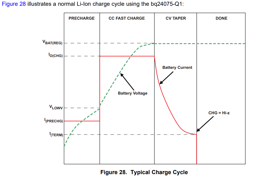
    Can I set R_ISET = 866 and expect constant 1A as in fig 28, and check for 1A because this is the final thing I want to achieve ,so that I can charge my 2500mAH battery in exactly 2.5 hours - 3 hours or to get constant 1A do I need to stay with R_ISET with 590E to achieve 1A.

    Issue 2:

    As Gautham had mentioned, and he is true that there is some drop in the input cable and I changed input cable and voltage at input capacitor is now 5V,But still not getting 1.5A constant current consumption. I was aiming for charge cycle as red graph in fig.28 as mentioned in datasheet and  I also attached it here.

    How do I get that?

    Issue 3:

    A point to note here, Input is 5V in RPS and getting the same voltage to board measured at C1 without battery connected to board, But as soon as I connect the battery voltage is getting dropped and varying as attached below at C1(at IC input pin capacitor) and charging current is varying between 0.6 and 1A but I am expecting something as in Fig.28 in datasheet. Is this drop normal or do I need pay attention to this?


    Issue 4:

    Board is also getting some warm. Does IC get heated up generally when charging at 1A charge rates or do I need pay attention to this?

    Issues in 1st Board:

    Issue 5(This is in another board):

    Playing with different cables suddenly I came across a new problem today and I had no clue why I am facing it. Input current is limited to 0.18A under load and no load conditions with new cable and previous cable also and I also tried increasing input voltage up to 6.5V previously it is 0.5A with 5V,but not having this issue in 2nd board.

    Earlier current consumption used to increase if connect  load(resistive using some pot) having  battery already connected at the same time but not having this issue in 2nd board..

    I suspect that I have switched my RPS ON and OFF multiple times having it connected to my board, may be that resulted in excessive input current in to BQ24075 at the time of switch ON, but IC condition is fine now and it is charging at 0.18A.How to bring IC back to normal condition and what may be the probable reason for this? Does this have any connection to fig.27 in datasheet.

    Thanks and Regards,

    P.Akhil.

  • Hi,

    Based on your data, it looks like the input voltage dropping may cause the output to drop and possibly the charge current to drop as well. With your configuration, this would be the reason why the charge current is reducing (DPPM). 

    Akhil Pendyala said:

    I was aiming for charge cycle as red graph in fig.28 as mentioned in datasheet and  I also attached it here.

    How do I get that?

    This is one charge cycle with a battery that requires pre-charging. This occurs over time with normal operation with the battery below 3V (the pre-charge to fast-charge transition threshold). 

    Akhil Pendyala said:

    But as soon as I connect the battery voltage is getting dropped and varying as attached below at C1(at IC input pin capacitor) and charging current is varying between 0.6 and 1A but I am expecting something as in Fig.28 in datasheet. Is this drop normal or do I need pay attention to this?

    This drop is not normal. This can be associated with the power supply not providing sufficient power or board connection issues.

    Akhil Pendyala said:
    Board is also getting some warm. Does IC get heated up generally when charging at 1A charge rates or do I need pay attention to this?

    The IC will generally heat naturally but not normally noticeable. The increased heat you may be seeing is most likely due to the increased power dissipation. For Thermal concerns in normal operation, please see Section 12.3 Thermal Considerations in the datasheet.

    Akhil Pendyala said:

    Playing with different cables suddenly I came across a new problem today and I had no clue why I am facing it. Input current is limited to 0.18A under load and no load conditions with new cable and previous cable also and I also tried increasing input voltage up to 6.5V previously it is 0.5A with 5V,but not having this issue in 2nd board.

    Earlier current consumption used to increase if connect  load(resistive using some pot) having  battery already connected at the same time but not having this issue in 2nd board..

    I suspect that I have switched my RPS ON and OFF multiple times having it connected to my board, may be that resulted in excessive input current in to BQ24075 at the time of switch ON, but IC condition is fine now and it is charging at 0.18A.How to bring IC back to normal condition and what may be the probable reason for this? Does this have any connection to fig.27 in datasheet.

    This does not have any connection to the battery charge profile. Current consumption should increase if the load current draw is increasing. When conducting the tests, ensure that the IC is not in thermal regulation. This can cause the device to lower the charge current. 

    For further diagnosing the issue, what is the voltage on /PGOOD, /CHG, and ISET when you see each current?