Hello,
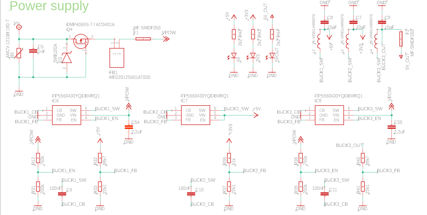
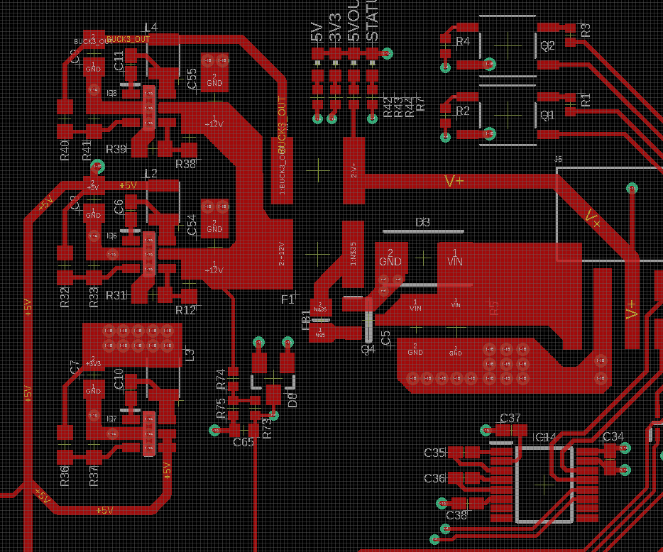
is it possible to power TPS560430 from another TPS560430?
I have 5V and 3,3V in my design, and i would like to feed the 3,3V buck from the 5V buck.
Best regards
Original question:

Hello,
is it possible to power TPS560430 from another TPS560430?
I have 5V and 3,3V in my design, and i would like to feed the 3,3V buck from the 5V buck.
Best regards