This thread has been locked.

If you have a related question, please click the "Ask a related question" button in the top right corner. The newly created question will be automatically linked to this question.

TPS2115A: Using IN1 as input for D1

Part Number: TPS2115A
Other Parts Discussed in Thread: TPS2121, TPS2115, , TPS2113A

Hi,

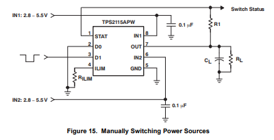
Our team decided to use TPS2115ADR as Power-OR solution for the board we are making. We decided to use the Manual Switching mode as demonstrated from the datasheet (image 1)

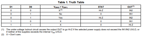
and using this truth table

From our understanding, the 1st and 4th row applies to manual switching mode.

We decided to use IN1 as the input to D1 such that, when IN1 is connected, D1 is pulled HI to IN1, and IN1 is chosen as OUT. However, when IN1 is not connected, if my understanding is correct, D1 is still pulled HI because of the internal pullup and thus will still choose IN1 (based on the truth table). So we wanted to make sure that D1 is either pulled HI to some voltage, or pulled LOW to follow the truth table.

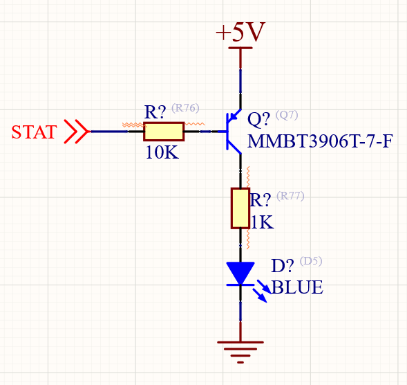
From the image below, we decided to implement a voltage divider (R1, R2) that supplies D1 when IN1 is connected and Pulled LOW (via the divider resistor R2) when IN1 is not connected. For reference, +5VDC:external supply; VBUS:5V from USB; and +5V is the output voltage. We want to prioritize external 5V (+5VDC) when it is present.

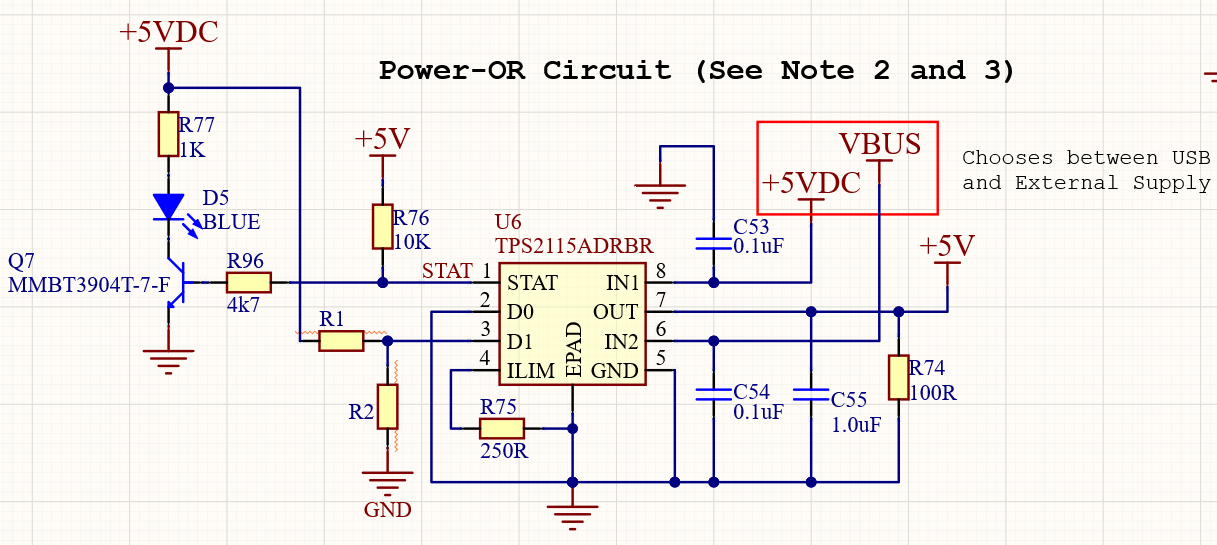
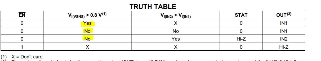
We are aware that the D1 can sink current as stated below. Our concern is the values of the resistor we could use to make this work. From my understanding, the resistor should be high enough to avoid sinking high current but must not be too high so that R2 works as a good pull-down resistor when IN1 is not connected.

Can you recommend values for R1 and R2 (or at least the order of magnitude) if I want to operate the D1 at at least 3.3V when IN1 is connected and pulled LOW via R2 when IN1 is not connected? Other comments are also welcome.

Many thanks,

Ramon

  • Some images above seem to be displayed incorrectly, here they are in order, they are from the datasheet

  • Ramon,

    Based on the goal of your circuit: Have you considered TPS2121 instead of TPS2115?

    Its a newer part, lower Ron, soft-start, adjustable current limit and overvoltage with resistor among other benefits. 

    the 1ku reel price is 4cents more.

    Also it is expressly designed for Prioritizing IN1 based on a resistor divider like your goal with TPS2115a. I think it could be a much better option for what you are trying to accomplish. 

    Another option to look at is TPS2113a which is very similar but better specced to TPS2115a if you need close to a P2P part as possible.

    Please let me know

    best

    Dimitri

  • Hi,

    Thanks for this. I am already looking at the datasheet. We want to power the board with either an external 5V source or the 5V from the USB but with priority to the external 5V whenever it is present. What mode of operation would you recommend to use? Both are 5V supplies, and we want it to autoswitch but give priority to external. If external is not present, then autoswitch to USB 5V. 

    Thanks again,

    Ramon

  • Ramon, 

    Understood. 

    I could recommend either TPS2113A or TPS2121 (the more modern of the two). 

    TPS2113A truth table is shown below. You can make a single resistor divider to VSNS and have exactly the functionality you want which is a better solution overall than using TPS2115. If you prefer the more robust and modern TPS2121 this will have the same functionality that you need with more features. 

    Please let me know if this answers your questions by pressing the green button. Let me know if you have further questions on this. 

    Best

    Dimitri

  • Hi Dimitri,

    I considered the TPS2121. Thanks. I would just like to ask if the circuit below would work as intended. I am using the XCOMP mode of the TPS2121, which means the ST pin is pulled H when IN1 is the output, and pulled L when IN2 is the output. I designed the simple circuit below that will light up the LED when IN2 is in use. The LED has Vf=2.8V, If=2mA. The PNP BJT has VCE,sat=0.4V Max, VEC,on = 0.95V and can drive up to Ic=200mA.  

    Thanks,

    Ramon

  • Ramon, 

    This circuit is exactly what we would recommend for LED indication from ST pin.

    THis will work fine. 

    Best

    Dimitri