This thread has been locked.

If you have a related question, please click the "Ask a related question" button in the top right corner. The newly created question will be automatically linked to this question.

BQ76952: Manual cell balancing does not work on few of the cells

Part Number: BQ76952
Other Parts Discussed in Thread: BQSTUDIO

We are using a custom board with 20 ohm resistance in series between BQ and cell terminal. A six cell battery is connected to BQ with the following connections:
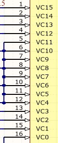
VC0: GND

VC1: Cell 1 

VC2: Cell 2

VC3: Cell 3

VC4-VC5: Cell 4

VC6-VC15: Cell 5

VC16: Cell 6

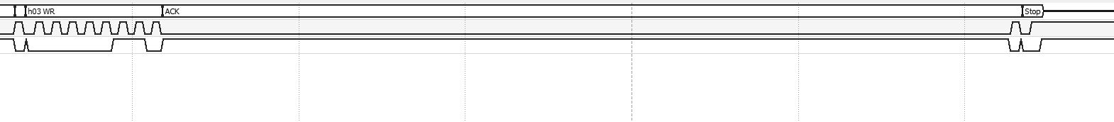
When we write to the CB_ACTIVE_CELLS register and read it back, it's what we expect when we're either clearing it or setting any of the first three cells to balance. However, when we try to set other bits, and read them back, we get 0x00. We can also use CBSTATUS2 and CBSTATUS3 to .verify that our loop successfully continues to activate balancing on. Cells 1, 2, and 3 (and we can see a voltage across their corresponding balance resistors), however, none of the other cells have apparently been balanced for any amount of time. We've also verified that the cell temperature reading is well within the default limits.

  • Hi Eohan,

    You connection seems ok from the description.  While I don't find a limitation in the technical reference manual set the cells used to the appropriate selection for cells.  Balancing interconnect is not expected.  Host controlled balancing should ignore checks for automatic balancing and limits are not expected.

    From one of the other inquiries you have, check your checksum on the balance command.  The CB_ACTIVE_CELLS sub command will not be accepted with an incorrect checksum.

  • WM5295 said:

    While I don't find a limitation in the technical reference manual set the cells used to the appropriate selection for cells.  Balancing interconnect is not expected.  Host controlled balancing should ignore checks for automatic balancing and limits are not expected.

    Could you rephrase this ? What do you mean by balancing interconnect is not expected ? What is the appropriate selection for cells ? 

    WM5295 said:

    From one of the other inquiries you have, check your checksum on the balance command.  The CB_ACTIVE_CELLS sub command will not be accepted with an incorrect checksum.

    This was one thing we checked after your comment. Verified that the checksum was accurate for the CB_ACTIVE_CELLS command
  • Hi Eohan,

    See the technical reference manual 13.3.2.19 Settings:Configuration:Vcell Mode.

    Vcell mode tells the part if a cell should be used for protections or not.  It does not describe its effect on balancing.    In 10.1 Cell Balancing Operation however it says " For autonomous balancing, the device will only balance non-adjacent cells in use (it does not consider inputs used to measure interconnect as cells in use). "  and goes on to say in host mode you should be able to balance what you want. 

    Check to be sure you have the Vcell Mode set correctly.  The document does not say host balancing is prevented on interconnect, but it does not seem reasonable to balance a wire. 

  • Hi, 

    Tried the 13.3.2.19 Settings:Configuration:Vcell Mode configuration and it did not have any effect on the balancing.

    I'm attaching the waveform for the command to balance cell 1 and another to balance cell 4. Cell 1 works and cell 4 doesn't Is there anything missing in the waveform. 

    setting cell 1 to balance (which works)

     setting cell 4 to balance (which does not work)

  • Hi Eohan,

    The waveforms are a bit interesting to read.

    When sending the cell balance command for 1 cell following the guidance on subcommands in the first paragraph of the technical reference manual I would send 08W 3e 83 00 01 00.  Then 08W 60 7B 06.  The 06 comes from the description in the next to last sentence of the paragraph 3.1 of the TRM: "The data length includes the two bytes in 0x3E and 0x3F, the two bytes in 0x60 and 0x61, and the length of the transfer buffer."  The checksum is calculated over the 4 bytes 83 00 01 00.

    The second waveform sequence you sent seems to be 08W 83 00 04 00 then 08W 60 74 03.

    The checksum would be the NOT of the sum of  83 00 04 00 (sum = 87).  NOT is 78.  So it would seem the 74 you are sending as the checksum for this command is wrong.  From the success with the first sequence apparently the part is tolerant of the length difference, but I would recommend the guidance of the technical reference manual.

  • Hi, 

    1. The waveforms seems right. The logic analyzer does not accurately decipher the numbers sent. If you look at the waveform they correspond to the right numbers. 
    2. An update on the cell voltage issue; we've actually seen it successfully balance all cells on one board in certain conditions. We noticed that in this case, a difference in cell voltages correlated with whether or not all cells would be balanced successfully.

      With cell values [3288, 3274, 3284, 3285, 3881, 3158], all 6 cells were balanced successfully.
      With both [3744, 3748, 3739, 3739, 3742, 3721] and [4003, 4019, 4013, 4036, 4022,4017], only the lowest three cells were balanced.

      While there is a general correlation; we can balance all cells when the voltages are low, we're finding it difficult to comprehend whats going on as results aren't consistently reproducible; sometimes one board will balance all cells while another won't on the same battery. Sometimes the same board and battery will balance 3 cells, sometimes 4.
    3. A 4s, 5s, 12s etc configuration has been tried but with similar arbitrary results. 


    It would be very helpful to understand what the actual logic looks like that switches the balance FETs, so that we can take into account any conditions that will cause a cell not to balance.

    Note that the firmware is the same for all of these tests. 

  • Hi Eohan,

    No additional logic diagram is available.  For manual balancing if you send the right data to set the bit to balance, the internal FET balances in its time.  See the balance apnote https://www.ti.com/lit/pdf/sluaa81 for waveform examples.  Voltage is not know to affect the balancing.  I typically observe balancing control with commands sent at low voltage for easier observation. 

    If you are allowing the part to balance autonomously be sure the impedance of the "cells" is low and the impedance of the path between the cells and part is low.  Balance current will pull on the cells and measurement times are short.  A high impedance cell or connection can give incorrect measurements compared to a meter measuring over a long time and resulting in decisions to balance the wrong cells.

  • WM5295 said:

    No additional logic diagram is available.  For manual balancing if you send the right data to set the bit to balance, the internal FET balances in its time.  See the balance apnote https://www.ti.com/lit/pdf/sluaa81 for waveform examples.  Voltage is not know to affect the balancing.  I typically observe balancing control with commands sent at low voltage for easier observation. 

    If you look at the waveform(not the interpreted numbers of the logic analyzer), the data looks right. Kindly confirm. 

    WM5295 said:

    If you are allowing the part to balance autonomously be sure the impedance of the "cells" is low and the impedance of the path between the cells and part is low.  Balance current will pull on the cells and measurement times are short.  A high impedance cell or connection can give incorrect measurements compared to a meter measuring over a long time and resulting in decisions to balance the wrong cells.

    We have tested this with both a battery(~1milliohm IR) and cell simlator with 100ohm effective IR. Both display the kind of unexpected behavior mentioned above
  • Hi Eohan,

    Again direct host control of balancing is not dependent on balancing.  The parts were tested in development and found to work.  Parts are tested in production.  If the part you are using might have been damaged, change it.

    In  your waveform I see the analyzer does sometimes miss interpret the waveform.  For example in the "cell 4 to balance (which does not work)" the command 0x83 looks like 0x83 in the waveform although the display says h41RD.  The checksum I calculate should be 0x78, but later in the waveform it shows 0x74 sent for the checksum byte. I see the length byte sent is 0x06.  I think you are describing intermittent success.  I don't know why or how checksum generation could be intermittent.

    Other than the wrong checksum, if your analyzer is having trouble understanding the waveform, could the waveform have artifacts which make it difficult for the IC to understand as well?  Waveform sensitivity could certainly be intermittent.

    <deleted message structure commment, length seems correct in the one checked>

  • Hi, 

    The data that is sent in the second waveform sequence is 08W 83 00 08 00 , the byte in picture is 0x08 not 0x04. So that should be the correct data. Please note that the analyzer is not detecting the right numbers for the waveform. 

    The I2C lines look very clear on the oscilloscope. 

    WM5295 said:

    Hi Eohan,

    Again direct host control of balancing is not dependent on balancing.  

    what do you mean by this ? 

    WM5295 said:

    The parts were tested in development and found to work.  Parts are tested in production.  If the part you are using might have been damaged, change it.

    We have tested over 15 different chips. All of them have this behavior.  We can change the voltage in the simulator and have different cells be balanced. This is one reason we are thinking there are some voltage based logic for the balancing. A threshold based condition does not explain the behavior entirely though. 

  • Hi Eohan,

    "Again direct host control of balancing is not dependent on balancing."

    I'm not sure if it was an incomplete thought or an attempt to say that with host balancing what you write is what you get to balance.

    I do see the sequence now and confirmed that 08W 83 00 08 00 followed by 08W 60 74 06 balanced cell 4.  It balanced until the timeout, it balanced at 4017 mV, 4022 mV and 4036 mV as well as several other voltages between 2 and 4.4V.

    If you have 15 working the same way it sounds like an algorithmic behavior.

    There are many configuration settings.  Are you using host balancing or autonomous balancing?  Can you describe the configuration and send the gg file and a log of the unexpected behavior?

  • We have a custom board that we are testing on. I assume gg file is for a devkit of TI ? 

    1. We are using host balancing. This is the outline of the code that is called before the balancing bytes being sent. 
    int bq76952::initBQ(void) {
      Wire->begin();
    
      // Unsealing
      subCommand(0x1404);
      waitForBuffer();
      subCommand(0x7236);
      waitForBuffer();
      subCommand(0xFFFF);
      waitForBuffer();
      subCommand(0xFFFF);
    
      // ~~~~~~~   Config update   ~~~~~~~ 
      volatile uint16_t reg=0;
     
      // Data Memory setup
      enterConfigUpdate();
      
      do 
      {
    	  reg = directCommandUnsigned(0x12);
      } while (!(reg & 1<<0));
      
      
      if (otp_prog) {
    	writeDataMemory(0x9237, 0x01, 1); // Prereg
    	writeDataMemory(0x9236, 0xFD, 1); // REG1 3v3, REG2 5v
    
    	delay(2);
    
    	// Just for verifying in debug
    	reg = readDataMemory(0x9237);
    	delay(2);
    	reg = readDataMemory(0x9236);
    	delay(2);
    	subCommand(0x00A1);
    	waitForBuffer();
    	reg = subCommandResponseInt(0);
      }
    
      if (n_therms == 0) {
    	  writeDataMemory(0x92FD, 0x00, 1); // TS1 Config
      } else if (n_therms == 2) {
    	  writeDataMemory(0x92FF, 0x07, 1); // TS3 Config
      }
      
      writeDataMemory(0x92FE, 0x0B, 1); // set TS2 pullups
    
      cc_gain = 7.4768 / (shunt_value * 0.001f);
      cap_gain = cc_gain * 298261.6178;
      writeBufferBlock(0x91A8, 0, 4, (uint8_t*)&cc_gain);
      writeBufferBlock(0x91AC, 0, 4, (uint8_t*)&cap_gain);
      resetQ(); // resets a coulomb counter on BQ
    
      uint8_t balance_config = 0x04;
      writeBufferBlock(0x9335, 0, 1, &balance_config);  // writes the balance config to the register.
      
      exitConfigUpdate();
      return 0;
    }

    2. We are also sending a command periodically to prevent the BQ from going to sleep. 

  • Hi Eohan,

    1. Yes, a gg file is a list of all parameter settings in the part (BQ76952), essentially the dump of the configuration with recognizable names, it can be output from BQStudio and loaded into another part.  Each development environment is a little different, some having better tools than others.  It may be useful at some point to pause your MCU and read all parameters from the BQ76952 with an independent tool such as BQStudio to check for unexpected parameter settings.

    I'm not particularly competent to review your code, you may need a software consultant to do that and look for any algorithmic or coding issues. In the segment above I see you configure the regulators, temperature sensors, and set the cell balancing configuration to allow balancing during sleep. (0x9335 set to 0x04) 

    Where cells are connected to the device and what is connected to various pins is also an important piece of knowledge.  In your question basically where are the cells connected.

    A log file is of course a list of conditions with time.  Depending on the environment these might be written by the host,, read from the host by an external program or emulator, or collected by an independent data logger. The data logger report can be less useful because while it will show currents, voltages, temperatures, it won't show device status or commands sent or register status (if something alters a register from the command sent).  The data logger can also show cell voltages during balancing going in unexpected directions, but can't give any insight into what the host was reading for voltages and why it might have sent the commands it chose. BQStudio logs parameters from the part but would not be useful in your situation since there could be bus collisions as neither host would expect the other.

    With a log file one would expect to see the voltages of the cells, the commands sent to balance the high cells as determined by the host algorithm and the voltage decrease on the high cells (or not as you have observed). A versatile log would also be able to show if the cell balance interval (timeout) was being set to some low value below the time that the balance command is set.  It is most efficient if your developer analyzes the log since they will be most familiar with the processes.  If your staff can't identify the issue the log may show us conditions to allow reproduction of the condition and check operation for some unexpected dependency.

    If you can isolate the unexpected behavior to a command we can look at that, similar to the cell 4 won't balance above which after the confusion of the data does seem to work fine here.   I would wonder if there is some process in your host which has the timeout set low or is overwriting the data after it is sent.  The parts are trusted as good, yet you see 15 perform the same wrong way, so there is something we are not understanding.  It is a recent part and I'm still learning a lot about it.

    What are you setting for Vcell Mode, and CB_ACTIVE_CELLS(), and where are the cells connected on the high voltage cells that you don't see balance?  Does CB_ACTIVE_CELLS() read back what you wrote?

    2. There is the SLEEP_DISABLE command which should persist until a config update or sleep enable.   You could also clear the SLEEP bit in the Settings:Configuration:Power Config  


  • We are not using a BQstudio, but a different custom board. We can read all the individual registers and output them in a text file or a csv file if you think you could help us. Alternatively, it would be much more faster if you tell us the specific registers that you'd like to know the values of, and we can find that. 

    It would seem that you would have access to the logic of the chip, since you have designed it, to find out if there are any logic flows that prevent the balancing of the cells. If there are no such logic that may prevent a cell from being balanced, then it seems like a silicon issue that is not reproducible in the dev boards that you may have ? 

    * For CB_ACTIVE_CELLS(), we're setting 1 bit at a time corresponding to the cell which is to be balanced. In the base of the previously outlined
    hardware setup, we're sending
    0x0001
    0x0002
    0x0004
    0x0008
    0x0020
    0x8000

    * We can always read back what we wrote to the balance register immediately after, but in the case of the cells which are not successfully balancing, the corresponding bit is set false the next time we read the register (a few seconds later). Again, it would be very convenient to know what can cause that.

    * As mentioned previously, we tried writing the corresponding cell bits in VCell Mode, but this had no effect on our results. Specifically, with the same cell setup, we wrote 0x802f (corresponding to the bits above)

  • Hi Eohan,

    What are the settings for COV and recovery hysteresis thresholds, and all settings for the BQ76952 technical reference manual section 13.3.11 Settings:Cell Balancing Config?

    How are the cells connected, are the cell tabs connected directly to the board or is there other resistance or impedance in the connection? 

  • Hi 

    * We have not using the custom calibration override feature; both the COV Threshold and COV Recovery Hysteresis were read back as being default; 86 & 2 respectively
    * We are also not enabling any protections, all settings which we set are shown in the previously posted init code. We have regulator settings (and nothing else) in OTP
    * Again, we're setting cell balance config to 0x04
    * The cells are connected from the 22 gauge balance wires of a LiPo pack, to a 2.54mm pitch connector on the PCB, and then through a few cm of PCB traces to the IC. The exact impedance is not known. The unused cells are shorted as shown below close to the chip. 

  • Hi Eohan,

    Cell Balance Config of 0x04 allows balance during sleep.  The technical reference manual does not say that it affects host balancing, thanks, I'll check that.

    Your original post said 6 cells, in your Jan 28 post you showed commands for 6 cells, but the schematic above shows 9 cells. Are you leaving inputs open?

    The connection you describe seems like a low resistance connection.

    The cell balancing will timeout every  Settings:Cell Balancing Config:Cell Balance Interval, default is 20s.  That seems longer than your "next time we read the register (a few seconds later)", but do you know when you actually write and read the register, and what values are sent and read when it is incorrect?

    All parts are believed to work the same unless damaged.  So far I can't duplicate your issue.  Certainly I will never be able to duplicate your code, but can you describe the specific sequence of values written and read from the part and anything you believe is related?  Is it voltage, or a specific bits sent, or time, or other communications or operations? 

  • WM5295 said:

    Your original post said 6 cells, in your Jan 28 post you showed commands for 6 cells, but the schematic above shows 9 cells. Are you leaving inputs open?

    We are not leaving any inputs open. That schematic was just a reference to to show how the wiring was done. For the configuration we are using we already mentioned that the wiring was 

    VC0: GND

    VC1: Cell 1 

    VC2: Cell 2

    VC3: Cell 3

    VC4-VC5: Cell 4

    VC6-VC15: Cell 5

    VC16: Cell 6

    WM5295 said:

    The cell balancing will timeout every  Settings:Cell Balancing Config:Cell Balance Interval, default is 20s.  That seems longer than your "next time we read the register (a few seconds later)", but do you know when you actually write and read the register, and what values are sent and read when it is incorrect?

    The few seconds would be 2 seconds in our case. We are also checking on an oscilloscope and the balancing timer to see if the balancing has been performed. 

    WM5295 said:

    All parts are believed to work the same unless damaged.  So far I can't duplicate your issue.  Certainly I will never be able to duplicate your code, but can you describe the specific sequence of values written and read from the part and anything you believe is related?  Is it voltage, or a specific bits sent, or time, or other communications or operations? 

    We couldn't find a correlation.

    • Sometimes changing the cell voltages a bit might cause some cells to balance, but sometimes not. The only "stable" thing we've see is that in a particular voltage setting, the cells that are balanced does not change. 
    • The lower "continuous" set of cells(cell 1-3) are always balancing. 

  • Hi Eohan,

    If I leave Vcell mode default of 0000 I can see balancing stop, casually it does not work.   It actually starts and terminates in about 10 ms. Cells are pulled into COV and the part stops balancing to evaluate the COV condition.  See description in the technical reference manual 10.2. "... COV alert ... balancing is immediately disabled."

    When I set the Vcell mode to 0x802F as you describe, balancing runs in my test where I am balancing one cell at a time. In the past you said Vcell mode had no effect in your test. What balancing value are you writing? 

  • WM5295 said:

    If I leave Vcell mode default of 0000 I can see balancing stop, casually it does not work.   It actually starts and terminates in about 10 ms. Cells are pulled into COV and the part stops balancing to evaluate the COV condition.  See description in the technical reference manual 10.2. "... COV alert ... balancing is immediately disabled."

    We are setting the Vcell mode to 0x802F like we mentioned previously. We tried setting it to different values (0x00, 0xFF etc) and that did NOT solve the problem. 

    Are there any other tests to debug the issue or is this an issue with the batch of BQ76952 chips we received ? 

  • Hi Eohan,

    Check your settings, and connections.  Perhaps adjust your voltages to see if it works at different voltages.  Change the number of cells you are balancing if you are pulling into a fault condition.so that the balancing terminates. If you are using cells corresponding to 0x802F that is the setting to use for Vcell mode.


  • Hi,

    Check your settings, and connections. 

    - we have done this many times and on different boards. 

    Perhaps adjust your voltages to see if it works at different voltages. 

    - We have tried multiple different voltages. We already updated on this thread about the balancing behavior (

    Change the number of cells you are balancing if you are pulling into a fault condition

    - reported the findings already that testing different cell count didn't solve the problem 

    .so that the balancing terminates. If you are using cells corresponding to 0x802F that is the setting to use for Vcell mode.

    - Again, this was tried and reported on the previous post. 

    We seem to be going round and round asking and answering the same questions over and over.

    Again, this issue could be due to some mistake on our part. But it doesn't help if support team hasn't gone through the entire conversation to understand and help resolve the problem. 

  • Hi Eohan,

    I think the main challenge in this debug is we are lacking the information we need to help you. Normally users would evaluate using the EVM and BQStudio first. The data we would normally request to help with this debug is the .gg.csv file from BQStudio (which contains all of the register settings) and a log file (this would show all of the registers from the Register screen of BQStudio. We would be particularly interested in seeing a log of the cell voltages, Safety Alert registers, Safety Status registers, Alarm Status registers and cell balancing registers. It would also be good to confirm the device version you are using to verify you are not using pre-production version of the device - this can be read with the 0x0002 subcommand. I think it is not likely you are using a pre-production version.

    I know you have said multiple times that you tried setting VCell Mode correctly and it did not fix the problem. I just want to make sure you understand this is necessary, it is not optional. 

    The issue you are describing has not been reported by any other users and we have not been able to reproduce it on our hardware. So we need as much information from you as possible to help narrow down the behavior. If you are using Host controlled balancing, the only things that might interrupt the balancing (assuming everything is set up correctly from the hardware and software side) is a Safety Alert or if the measured temperature is outside of the Cell Balancing temperature limits you programmed. You said that no protections are enabled - did you write to the registers to disable the protections that are enabled by default? For example, if an over-voltage alert occurs, it will stop balancing. It is important to read from the SafetyAlert registers frequently to see if this is triggering because it is not latched until  it has occurred for the over-voltage delay limit.

    Without enough data, all we can do is make guesses which slows down the debug process. Please try to consolidate all of your information - maybe attaching a document might be easier since the thread is long now and difficult to comb through.

    Best regards,

    Matt

  • Is there a non public forum where we can share data that is confidential ? 

  • Hi Eohan,

    I sent you an E2E connection request. You can accept and send me a private message so it will not be shown on the forum. Please include as much detail as you can.

    Thanks,

    Matt