This thread has been locked.

If you have a related question, please click the "Ask a related question" button in the top right corner. The newly created question will be automatically linked to this question.

TPS1HB08-Q1: How much time during overcurrent is needed for shutdown?

Part Number: TPS1HB08-Q1

Hi team, 

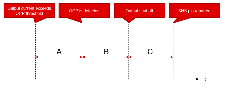
Could you tell me how much time during overcurrent, which exceeds current limit threshold set by external resistor for TPS1HB08A-Q1, is required for shutdown or current limit event?

I guess very short term overcurrent cannot be detected by TPS1HB08A-Q1 and it would have the parameter for minimum duration to detect overcurrent, is it correct?

Regards,
Ochi

  • Hi Yoshiki, 

    Once an overcurrent event has been detected, a fast trip response of 7us will take place before the device starts to regulate or shut off the output current. Let us know if you have any further questions. 

  • Hi Francisco, 

    I understood that there is 7us between overcurrent event detection and shutting off output current .

    How much deglitch time, when output current exceeds the current limit threshold, is needed to detect overcurrent event? I would like to know overcurrent detection sensitivity.

    Regards,
    Ochi

  • Hi Yoshiki, 

    This is not a specified value, however,  you can typically expect 50us from the time the current limit occurs to the time it is reported on the SNS pin. 

  • Hi Francisco, 

    Could you confirm me my whether understanding is correct or not? In addition, do you mean duration A (or OCP deglitch time) is not specified, is it correct?

    Duration A: How much time is it required?

    Duration B: Fast trip response 7us from OCP detected to output shut off

    Duration B+C: SNS pin reported response 50us 

    Regards,
    Ochi

  • Above figure is for reference for my questions 

  • Hi Yoshiki, 

    We are checking this internally and I will get back to you as soon as get an answer here. 

  • Hi Yoshiki, 

    Current limit accuracy for the High Side Switches is different for instantaneous over-current events and slow current creeping events. When the current limit is detected instantaneously when the FET in the current mirror is saturated by a fast increment of load current. However, for slow current increase this FET will remain in the linear region affecting the current limit accuracy. The following application note, section 4.1 refers to this issue more in dept.

    https://www.ti.com/lit/an/slva859b/slva859b.pdf

  • Hi team, 

    Thank you for your supporting. 

    I took a look at https://www.ti.com/lit/an/slva859b/slva859b.pdf which says that " It does not affect the lower on resistance TPSxHBxx devices due to differences between the device architectures." 
    I understood that TPS1HB08-Q1 has no current limit accuracy problem @ slow current creeping events, is my understanding correct?

    Again, Could you confirm me my whether understanding is correct or not? In addition, do you mean duration A (or OCP deglitch time) is not specified, is it correct?

    Duration A: How much time is it required?

    Duration B: Fast trip response 7us from OCP detected to output shut off

    Duration B+C: SNS pin reported response 50us 

    Reference to https://www.ti.com/lit/an/slva859b/slva859b.pdf
    The current limiting accuracy for TPSxHxxx devices is different between instantaneous over-current events and slow current creeping events. Current creeping is defined as a fault that results in the slow increment of load current from a normal operating level to the set current limit. It does not affect the lower on resistance TPSxHBxx devices due to differences between the device architectures. Due to the electrical characteristics of the sense FET in the current mirroring circuitry of the affected devices, the ratio of the load current to the mirrored current is only defined while the FET is in its saturation region.

    Regards,
    Ochi

  • Hi Ochi, 

    Your understanding is correct with this device. The device accuracy should not be affected by this slow current. I am asking internally to see if there is a way to obtain this data. Another option I am considering if to try to measure this time on the lab and provide you a reference value to consider when using the devices. I should have an answer here shortly. 

  • Hi Ochi, 

    I was able to get some answer for the questions here. 

    A = will be a 3us current limit trip to maximum value. 

    B = Depends on what conditions you have. The FET turn off will follow the slew rate control as defined in the datasheet. 

    c = Correct, 50us should be the expected value here. 

    I hope this answers this question here.