This thread has been locked.

If you have a related question, please click the "Ask a related question" button in the top right corner. The newly created question will be automatically linked to this question.

BQ27750: BQ27750 can not charge after CUV trigger

Part Number: BQ27750

CUV parameters:
- Threshold: 3500mV
- Delay: 2s
- Recovery: 3600mV

In protection configuration, I enable CUV_RECOV_CHG to recovery CUV protection as charge is available.
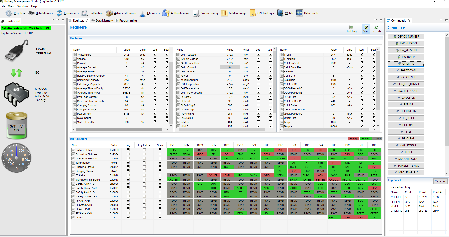
I just enable CUV protection and disabled all other. After the BQ27750 meets the CUV protection condition, it turn off DSG FET to terminate discharge and CHG FET remains ON. Then I connect charger to recharge the sensor but it can't charge and the current is always zero.

I wonder why the bq27750 cannot charge while CHG FET is ON and does not have any protection condition to disable charging. If the device is charged, CUV protection condition will be recovery.
I tested with BQ27750EVM-837 module with BQStudio. I use BAT with CHEMID is 0x0128. The sensor has passed calibration and learning cycle.

Thank you. 

  • Here is my screen shot and my golden image file attachment. The charger is connecting but the BQ27750 monitors the current as 0mA and I make sure my charger is good.


    5228.golden_image.zip

  • Hello,

    Is this with a custom PCB or the EVM? When the DSG FET is turned off, the charge current will have to go through the body diode of the DSG FET to charge the battery. Sometimes this can impede on charging. Are you only seeing this issue when the DSG FET is off?

    Sincerely,

    Wyatt Keller

  • Thank you for responding.

    I tested and got the same results on both custom PCB and the EVM.

    Another test case proving that DSG FET is off makes device cannot charge. I tested on bq27750EVM and used command 0x001F to turn on/off CHG FET and 0x0020 to turn on/off DSG FET with BQStudio.
    First, I send commands 0x0022 to disable both DSG FET and CHG FET while they are enabled. Then I send command 0x001F to trigger CHG FET. I see the XCHG bit and CHG bit at Operation status A are toggled (RED to GREEN for XCHG bit and GREEN to RED for CHG bit). I used VOM to measure voltage between TP5 pin and TP4 pin and measured result is about 13V, CHG FET was ON. Measured voltage between TP5 and TP3 is 0V, DSG FET was OFF. Next, I connect charger but device cannot charge.

    And there is the strange problem. When I connect and disconnect immediately  the FP5 jumper to short FET PYPASS, the device is charging. Nothing changes at the Bit Register window, but now, I see measured voltage between TP5 and TP3 is about 13V. Then I disconnect and reconnect the charger, the device cannot charger. I wonder why the DSG FET is ON but the DSG bit at Operation Status A indicates that DSG FET is OFF? Why is device charging after FET PYPASS is connected and disconnected immediately. Why is device charging but it cannot charge after reconnecting the charger in my test case above?

  • Hi,

    I have designed schemes to safely charge and discharge batteries. The charger sensor is BQ25619 and the fault protection sensor is BQ27750.
    I have tested and have only encountered one problem that I described before. But I am not sure in production it will be stable. Could you help me review the schematics? Is it well designed? Do you have any advice for my design?

  • Hello,

    This is most likely caused by the body diode of the FETs, if you increase your charging voltage further it should charge again. Some of our gauges have a body diode protection that won't allow too much current through the body diodes as well.

    Sincerely,

    Wyatt Keller

  • Thank you for responding

    I use a charger with charging voltage of around 4.2V and my battery type is GRP603533-3.7V-630mAh which a maximum charger voltage of 4.2V. How to increase the charging voltage as you mentioned? Why dose DSG FET impede on charging? Is it a BQ27750 Hardware BUG?

  • Hello,

    This is not a bug, it has to do with the characteristics of the FETs. Your CUV is very high for most applications, usually CUV is around 3V or lower. In these normal cases the voltage difference would be high enough between battery and charger to enable the body diode and start charging.

    Sincerely,

    Wyatt Keller

  • Thanks for the reply. The answer helps me clear up the problem.

    This is my design schemes to safely charge and discharge batteries. The charger sensor is BQ25619 and the fault protection sensor is BQ27750.
    I have tested and have only encountered one problem that I described before. But I am not sure in production it will be stable. Could you help me review the schematics? Is it well designed? Do you have any advice for my design?

    Thank you.

  • Hello,

    The design looks fine to me, this issue is related to the CUV threshold you have selected which is very close to the max charge voltage in terms of the diode drop of the body diode. The battery voltage needs to be greater than 4.2V-0.7v (diode drop) or 3.5V to charge. It looks like this is the exact voltage for your threshold so it may not charge depending on the diode drop.

    Sincerely,

    Wyatt Keller