This thread has been locked.

If you have a related question, please click the "Ask a related question" button in the top right corner. The newly created question will be automatically linked to this question.

LM3478: Please review the schematic (too many heat on diode and FET)

Part Number: LM3478
Other Parts Discussed in Thread: LM5122

Hello TI experts,

my customer made a sample PCB with LM3478, and they have a heat problem.

the schematic is as below;

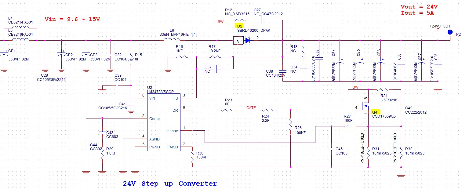
the output current is variable from 3A to 5A.

in 3A output situation, the temperature of Q4 is about 90℃.

and in 5A output situation, the temperature of Q4 is about 130℃ after 1 minutes. and after 1 minutes, Q4 is dead and no longer working because of the heat.

my question is;

1) what is the maximum value of voltage and current for the output?

2) can I improve this heat problem by changing the component or value?

3) how about the layout? is there any recommended layout for this part? if yes, does it consider heat problem?

please check this issue. Thanks.

Best regards,

Chase

  • Hi Chase,

    Thank you for using LM3478. Before we go in to details, could you please let me know at what input voltage they have the overheat issue?

    Thanks,

    Yinsong

  • Hi Yinsong,

    i asked customer, they tested with 10V power supply when have overheat issue.

    and usually they use one of the power source, the battery(9.6V~12.6V) or SMPS adapter (15V)

    Best regards,

    Chase

  • Hi Chase,

    Thank you. I checked that the Rdson of Q4 is pretty small. Do they have the SW waveform so that I can further investigate this issue? Also, please check if they have the inductor current waveform. Since LM3478 is a controller, there is no theoretical fixed limitation of the load. But first we need to make sure that the controller is working properly. As for the layout, the key is to minimize the AC loop. But again, that would not affect the temperature much as it is working. That being said, there are some techniques for helping the MOSFET heat dissipation layout-wise, but we let's check their waveforms first.

    Thanks,

    Yinsong

  • Hi Yinsong,

    because my customer do not have current measure equipment, i can only provide voltage waveform.

    1. switching frequency : 9.4us

    2. when the Q4 gate is on, voltage spark occurs after 77.5ns.


    please review this 2 waveforms.

    and I have more question

    1. Rdson of Q4 means the package of FET? should I use larger package for Q4?

    2. you said that there is no theoretical fixed limitation of the load. then what does "peak driver output current=1A" mean on datasheet 4page?

    3. please refer the following url;

    https://e2e.ti.com/support/power-management/f/196/t/954381?tisearch=e2e-sitesearch&keymatch=lm3478

    the expert said that large current can cause excessive heat problem in the rectifier diode, and he recommended LM5122. What do you think about it?

    and my customer will test with LM3478 EVM. i will share the result when the test is done.

    please check those issues. Thanks.

    Best regards,

    Chase

  • Hi Chase,

    It's fine if they cannot provide the current waveform, please check if they can provide the input current value. That will help me estimate the loss of the MOSFET. Also, I would like to make sure, is the SW waveform you show here stable when capture it? meaning that it always looks like this and there is no jumping, duty cycle loss, etc. Regarding your questions.

    1. The on-resistance of the FET and it claims 1mOhm in the datasheet which is pretty good. It's relationship at high temperature is also ok as shown in the datasheet.

    2. 1A is the peak current that can flow through the gate to drive the FET. It relates to the switching speed of the FET but is not related to the load current.

    3. For 10A load, I would also recommend using a synchronous rectifier but for 5A load, it might still be ok to use a schottky diode. It's all about thermal performance, which is what we are trying to address here. What temperature do they see on the diode? If the diode is overheating, it could heats up the FET as well.

    Thanks,

    Yinsong

  • Hi Yinsong,

    today I can update some status about this problem.

    1. about input current value, please see the table below. they tested each current step to calculate efficiency.

    2. yes, SW waveform is just like captured. even it has very very little spike on rising edge, but i think this does not have problem.

    and there is no jumping and duty cycle loss.

    and my customer said that the SW(Drain of FET) waveform is always similar but Gate of FET waveform is quite different.

    more output current, the red circle value is higher. (please see the capture image below, maybe this is obvious.)

    3. about diode, we can see similar high temperature on it. comparing to FET, diode have 10~20℃ more temperature. more output current, diode have higher temperature. (of course.)

    Please check this issue, and let me know if you have something to advise.

    Best regards,

    Chase

  • Hi Chase,

    There are two things I noticed here that worth further investigation.

    1. The switching time looks pretty long with the miller plateau they captured here. This could be a reason of the heat -- switching loss. But considering the frequency is only 100kHz this is not very likely. I'll check the datasheet of the MOSFET and give a calculation.

    2. The diode can also heat up the FET and the board. I'll take a closer look at the diode datasheet as well.

    Thanks,

    Yinsong

  • Hi Yinsong,

    Thank you for your reply.

    If there is anything I test for your analysis, please tell me.

    Best regards,

    Chase

  • Hi Chase,

    Thank you for your patience.

    I have checked the two things mentioned above. The major issue I found is with the diode. Its forward voltage is too high, around 1V. Please try to find a schottky diode with voltage around 0.5V. The FET could also heat up by itself as the switching time is very large (even though the frequency is low). Selecting the FET is always a tradeoff but in this case, as the switching loss may dominate, a FET with smaller Qg with the price of higher Rdson could be a better choice. I would start with the diode first as it has higher temperature.

    Thanks,

    Yinsong