This thread has been locked.

If you have a related question, please click the "Ask a related question" button in the top right corner. The newly created question will be automatically linked to this question.

BQ25611D D+/D- Multiplexing

Part Number: BQ25611D
Other Parts Discussed in Thread: TUSB320, BQ25619, TS3USB221

Dear Sirs,

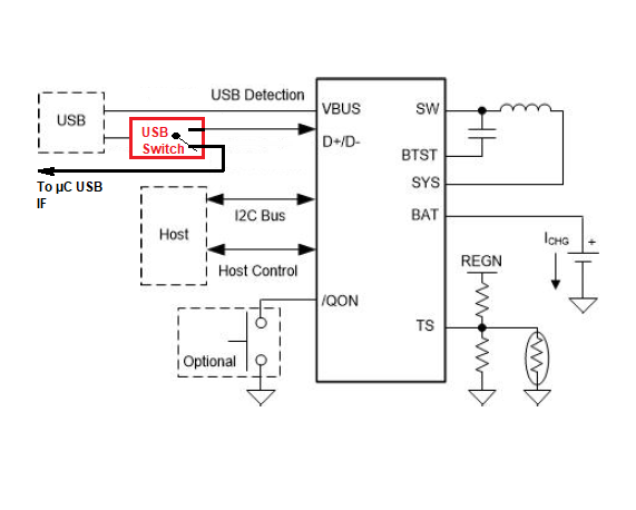
we would like to use BQ25611D in our design for lithium cell charging and system supply. I’ve got a question about implementation of that device. When the charger detection is completed, we would switch over USB interface to the MCU. Do you think, BQ25611D will continue the normal charger operation without D+/D- signals? Can detaching of those signals cause any errors?

Thank you very much in advance.

Best Regards.

Vitali

  • Vitali,

    This is an acceptable method. After BC1.2 detection is completed on D+/D- the connection to the pins can be broken without causing any issues. Please remember to reconnect D+/D- to the BQ25611D when the USB connection is removed.

    Best Regards,

    Ricardo

  • Hello Ricardo,

    thank you for that.

    I've got additional questions about BQ25611D

    1. Is that enough to check the "INT_N" status to recognize the input source detection is completed? Or should MCU check the I2C register status (IINDPM)?

    2. Our customer wishes an USB-C-Interface, so we have to implement a CC-Pin detection as well. BQ25611D doesn't support that, we actually use TUSB320RWBR for it. Can BQ25611D interact with TUSB320RWBR via I2C-Interface? Do you know better solution for that?

    Best Regards.

    Vitali

  • Vitali,

    1. Is that enough to check the "INT_N" status to recognize the input source detection is completed? Or should MCU check the I2C register status (IINDPM)?

    Waiting for the second /INT event during power up should be sufficient.

    2. Our customer wishes an USB-C-Interface, so we have to implement a CC-Pin detection as well. BQ25611D doesn't support that, we actually use TUSB320RWBR for it. Can BQ25611D interact with TUSB320RWBR via I2C-Interface? Do you know better solution for that?

    Looking at the application information for TUSB320 it seems the TUSB320 would negotiate a role and communicate to a host and that host would communicate to the BQ device.

    I would suggest creating a new thread to reach the TUSB320 team for confirmation.

    Best Regards,

    Ricardo

  • Thank you for that, Ricardo,

    that helps a lot.

    One question about Vsys: as I learned from datasheet “Vsys” is mostly slightly about battery voltage. I’m not sure about boost mode: as far as I see “Vsys” can be “boosted”, but “Vbus” is only an input, (no reverse boost operation), is that right? In other words: “Vsys” can be the boosted voltage for (another) USB OTG interface?

    Best Regards

    Vitali

  • Thank you for that, Ricardo,

    that helps a lot.

    One question about "Vsys": as I learned from datasheet “Vsys” is mostly slightly about battery voltage. I’m not sure about boost mode: as far as I see “Vsys” can be “boosted”, but “Vbus” is only an input, (no reverse boost operation), is that right? In other words: “Vsys” can be the boosted voltage for (another) USB OTG interface?

    Best Regards

    Vitali

  • Vitali,

    Boost mode actually produces a regulated output on VBUS. 

    In this configuration the battery voltage is boosted to produce an output to the VBUS pin. this output is typically used to charge an accessory device. If this is not desired, the BQ25619 can boost and produce an output on PMID rather than VBUS.

    Best Regards,

    Ricardo

  • OK, thank you very much Ricardo,

    in our understanding of boost mode, Q3 is the converter switch, Q2 is the flyback diode, Q4 is turned permanently off and Q1 is always on. In this way we have boost voltage on VBUS-Pin. Is that right?

    Best Regards

    Vitali

  • Vitali,

    This is not correct. Q4 is fully on as the battery becomes the power source. Q3 and Q2 will switch synchronously acting as a synchronous boost converter. Q1 will be fully on so as to deliver an output voltage to VBUS. 

    Best Regards,

    Ricardo

  • Hello Ricardo,

    thank you very much.

    Best Regards

    Vitai

  • Hello Ricardo,

    I've got another question about BQ25611D.

    Is that possible to supply a USB mux (TS3USB221) from internal LDO from pin REGN (4,7V)?  I've learned that LDO is running when the VBUS is available, so I could supply TS3USB221in this way. That bus switch suppports BC 1.2 as well, I would use a series diode to obtain 3,7volts. What do you think about it?

    Best Regards

    Vitali 

  • Vitali,

    This is possible, but be aware of I_REGN's current limit of 50 mA. Please verify the worst case scenario for your current draw of REGN (resistor networks, LEDs, etc.). The TS3USB221 requires fairly low currents, so I am fairly confident this will not be an issue.

    Best Regards,

    Ricardo

  • Ok, thanks for that, Ricardo,

    1. Is that correct that REGN LDO doesn't run in battery operation? It's chapter 9.3.2 in the datasheet:

    9.3.2 Device Power Up from Battery without Input Source
    If only the battery is present and the voltage is above depletion threshold (VBAT _DPLZ), the BATFET turns on and
    connects the battery to the system. The REGN stays off to minimize the quiescent current.

    And when the input source (USB) will be connected, the REGN LDO is turned on again.

    2. As far as I see REGN LDO supplies the source detection logic for D+/D- for charging, is that correct?

    Best Regards

    Vitali

  • Vitali,

    1. Is that correct that REGN LDO doesn't run in battery operation?

    Correct

    2. As far as I see REGN LDO supplies the source detection logic for D+/D- for charging, is that correct?

    I cannot comment on those internals for IP reasons.

    Best Regards,

    Ricardo

  • Thank you for that, Ricardo.

    Best Regards.