This thread has been locked.

If you have a related question, please click the "Ask a related question" button in the top right corner. The newly created question will be automatically linked to this question.

LM5116: Over Current Protection Failure

Part Number: LM5116

Hi TI expert,

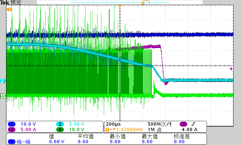
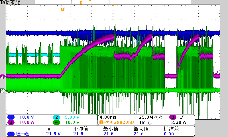
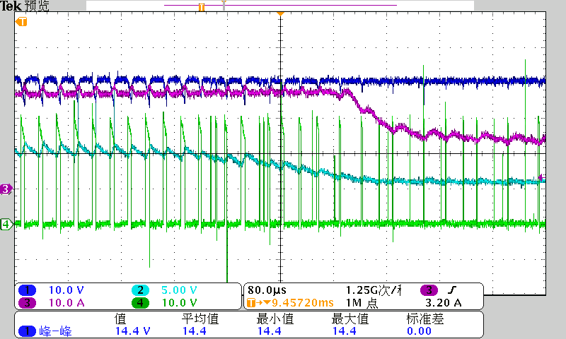
Find Over Current Protection Failure here.

Seems on issue board, switching not stopped, and have several acyclic pulse (just happen the position where the switching should get closed). Can you help analysis the possible cause?

CH1 Dark Blue: Input

CH2 Light Blue: Output

CH3 Pink: Output Current

CH4 Green: SW Point

Using EVAL LM5116-12:

30V IN, 12V OUT, 0.1R Load Transient Added

Issue Self-designed Board:

30V IN, 7.5V OUT, 0.1R Load Transient Added

B R,

Jayce Luo

  • Hi Jayce,

    Have you hiccup configured similar to the EVM? Please fill out and send the LM5116 Excel quickstart calculator for this design. Send the schematic too.

    Regards,

    Tim

  • Hi Tim,

    Any update?

    B R,

    Jayce L

  • Hi Jayce,

    We need to see the schematic and a completed quickstart calculator as requested.

    For a 7.5V output, I recommend not using VCCX (tie that pin to GND to disable). Also, the high-side FET has a large voltage drop based on what appears to be the SW voltage above - this indicates a high Rdson FET. And the current seems to be ~25A, quite high. 

    Please confirm what each scope channel refers to in the waveforms above, e.g. VIN, VOUT, etc.

    Regards,

    Tim

  • Hi Tim,

    Please check schematic and quickstart calculator in the email I send to you.

    I explained the  relationship between colors and waveforms in my questions description, and now repeat as below:

    CH1 Dark Blue: VIN

    CH2 Light Blue: VOUT

    CH3 Pink: Output Current

    CH4 Green: SW Point Voltage to GND

    Thanks.

    B R,

    Jayce

  • HI Jayce,

    Got your email, thank you.

    I notice the current sense resistor is only 2mOhm. This gives a very high current limit (based on the 110mV CS threshold), especially given that the full-load current spec is only 10A.

    I notice that the output current is getting up to 30A (Ch3) in the scope waveforms above - please check that the inductor is rated for such high current. My recommendation is to select the current limit setpoint around 15A to provide a reasonable 50% margin above the rated full load spec. Retesting with such a configuration results in less stress on the power stage, lower temperature rise, and more reliable operation.

    Regards,

    Tim