This thread has been locked.

If you have a related question, please click the "Ask a related question" button in the top right corner. The newly created question will be automatically linked to this question.

UCC2897A: Design review for UCC2897A active clamp 250W...

Part Number: UCC2897A
Other Parts Discussed in Thread: UCC27511

Dear Sirs,

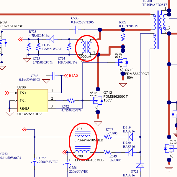
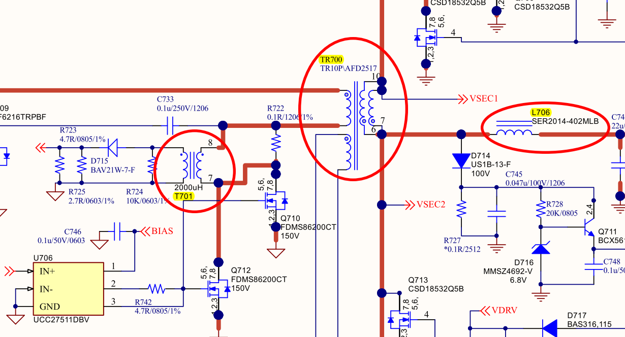
Could you help to review the schematics if there is any problem for 250W active clamp design?

Thanks.

Design spec.

=====================================

AC19.2V ~ 31.2V ( Vnom = AC24V )

PFC boost to 60V

DC Output 12V/21A

=====================================

Forward Transformer

  • Isolation transformer :

PQ3220 /  Np : Ns : Naux = 4Ts : 2Ts : 2Ts / Lp : 13.5uH

Na (匝數比) : 2

  • Secondary side energy storage inductor :

- N1^2*AL = N1^2 * 7310n = 13.33uH = N = 3.3Ts  use 4Ts

PQ3220 ( AL = 7310 )  / 13.33uH / 20Ts


 ===================================================

  1. Please help to check if the spec. of all PQ3320 (core PC40) are OK or not?
  2. CS (how to calculate CT/ how to calculate Aux inductor?
  3. Any problem for the schematics?

2476.UCC2897A_SLUC662_12V_21A.xlsx

1016.BT_forwad DC12V_21A for 250W.pdf

  • Hi Peter,

    Most everything looks in place for the design specs you've described. The only comment might be about the use of the UCC27511 gate driver ICs. Each of the drivers you have shown only has 0.1uF on VDD but you are driving parallel MOSFETs that most likely have gate charge of ~70nC on the primary MOSFETs and ~90nC for the parallel combination on the SR. I would recommend to have two capacitors in parallel as described below. Also, you may consider dedicated gate resistors for each MOSFET being driven.

    Good luck and thanks for connecting through E2E,

    Steve M

  • Hi Steven,

    Thanks for your reply!

    Customer will add Cap in parallel with VDD.

    Please also help to check if there is any problem with the design of TR700 and L706 attached file.

    And, for the T701 spec in schematics, can you help to give the suggestion for customer?

    Thanks.

    TR700.xls

  • Peter,

    L706-708 are off the shelf catalog indictors and can easily be adjusted by changing their value. Larger inductor for less AC ripple current, more DC loss, smaller inductor for more AC ripple current, less DC loss. The PQ3230 custom forward transformer calculations look correct for a starting point but the transformers (custom magnetics) are optimized by iteration. You may have to modify turns ratio, change winding structure, wire type, etc - the construction of the transformer is even more important than just getting the calculations correct. T701 is a CS transformer but please do not install R722 while T701 is installed. R722 is a short across the winding of T701, pins 8-7.

    Regards,

    Steve M

  • Hi Steve,

    Thanks for your reply.

    However, customer still needs your help to suggest the solution/components spec. more exactly!

    1. L706~L708, customer will design with PQ3220, could you help to suggest the turn ratio and L value for reference?

    2. For T701, the wire type did not determine yet! However, could you also help to suggest the turn ratio and L value

    Thanks.  

  • Peter,

    Try reading through SLUA535A...specifically:

    1. Section 4.1.1: output inductor
    2. Section 4.2: Transformer
    3. Section 4.6: current sensing transformer

    The output inductor and current sense transformer are straight forward off the shelf components available from your favorite magnetics vendor or disty. The transformer is going to be custom and so either you will need to design it yourself (Ferrite core, bobbin, wire) or you can provide a detailed spec and work with a custom magnetics vendor willing to provide samples. TI's focus is on semiconductors and so we don't usually recommend one magnetics vendor over another but if you look through our EVM User Guides, you will see names of vendors we've chosen.

    Good Luck,

    Steve M