This thread has been locked.

If you have a related question, please click the "Ask a related question" button in the top right corner. The newly created question will be automatically linked to this question.

LM27402: Startup hicupp with 12V to 1V @ 14A regulator design

Part Number: LM27402

Hi,

We are facing issue with LM27402 switching regulator for 1V @ 14A output from 12V input. During startup itself regulator is going into OCP hiccup mode and its continue in that. Final load to this regulator will be around 10A only.

We tried reducing the load by isolating some of the ICs at load, and still it is behaving same.

Tried changing soft start capacitor (C1500) to 1uF, even then issue persist. Please review schematic and let us know any changes required?

Attached below

1. Schematic section of 1V

Inductor part used is XAL6030-331MEB.

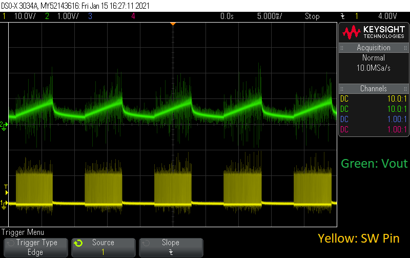
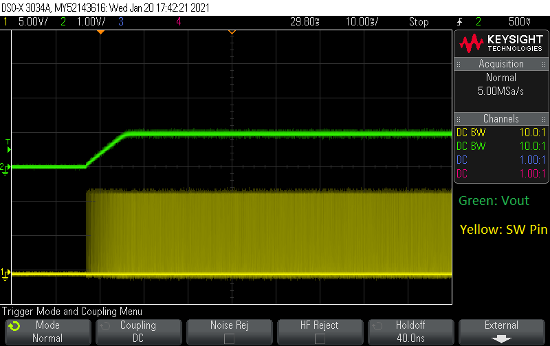
2. Regulator output waveform and SW pin waveform

Thanks,

Jijesh

  • Added schematic section and output waveform

    Thanks,

    JijeshNSP_V1P0.pdf

  • Hi ,

    It looks like you have 4.22kohm resistors on both sides of C1498 current sense cap. You should only have it on the CS- side as shown on Figure 33 on p. 23 of the datasheet. Try changing R936 to 0ohm and see if the OCP hiccup is still occurring.

    The Rset resistor (R942 in your design) is what sets the voltage offset between CS+ and CS- pins and sets the current limit trip point of the current sense comparator. You can see the current sense comparator in the block diagram on p.12 Section 7.2 of the datasheet.

    Regards,
    Kris

  • Hi Kris,

    Thanks for a quick response. I will try changing R936 to 0ohm and let you know.

    Actually we implemented the 12V to 1V schematic section based on TI's webench simulation and suggested values.

    Attached webench simulation output for your reference.

    LM27402SQ 11.5V-12.5V to 1V @ 14A.pdf

    Thanks,

    Jijesh

  • Hi Kris,

    Issue persist even after replacing R936 with 0ohm.

    We have tried changing switching frequency close to 1MHz by replacing R957 with 4.7K and all other current sense, compensation and FB network remain same. In this mode startup OCP hiccup is not there, but Vout is not stable and randomly OCP hiccup and Vout is turned OFF and restarted.

    Other workaround we tried is removing around 18 x 10uF capacitors from actual load. With this reduced load capacitors and at 1MHz switching frequency Vout looks to be stable.

    Please suggest necessary modification to get stable Vout with actual load capacitor and with switching frequency around 700KHz

    Thanks,

    Jijesh

  • Hi ,

    Sorry, you're right, the R936 in line with CS+ will not help. I was thinking about the circuit incorrectly.

    I will take a deeper look at your schematic when I am back in the office on Monday, but if you are trying to debug this right now, I suggest trying to simulate your circuit using the PSPICE model and also analyzing your design using the Excel calculator tool on the LM27402 product folder: https://www.ti.com/product/LM27402#design-development

    I will be doing the same on Monday.

    Regards,
    Kris

  • Hi ,

    I filled the Excel calculator with your design conditions and actual output capacitance (3*22uF + 18*10uF) and have attached it here. The compensation component values under Step 7 are quite different from what you currently have in your design.

    Please try using the compensation values shown in the Excel.

    /cfs-file/__key/communityserver-discussions-components-files/196/LM27402DesignCalculator.xls

    Regards,
    Kris

  • Hi Kris,

    Thanks for your reply.

    Actually the removed 18 x 10uF capacitors are placed far from LM27402 switching regulator. These are bulk caps for ethernet Switch and PHY distributed around  the chips. Should we consider those capacitors also as output capacitor for LM27402? If then the load capacitor will be huge and TI's webench also didn't ask about final load capacitor in the design.

    Thanks,

    Jijesh

  • ,

    If there is enough path resistance/inductance or if you have something like a ferrite bead before the additional output capacitors at the loads, then these additional output capacitors may not affect the LM27402 stability as they will be isolated from the regulator.

    But if you have big, wide power planes or pours from the LM27402 output to these load capacitors, then you should consider these additional output capacitors as part of the regulator design.

    Before you try changing the compensation as I previously suggested, perhaps another quick thing you can try first is to change R942 to a much higher value (say 3x or 4x your current value) to set the current limit higher, and see if the hiccup behavior changes. You can do this with your original frequency and total output cap connected. Your observation that increasing the frequency helped makes me think it could still be an issue with the current limit design, since the higher frequency will lower the peak inductor current. In case you haven't yet, have you double checked the R942 resistor value is the expected 4.22kohm?

  • Hi Kris,

    Thanks for your clarification on output capacitor.

    On our board before we have around 300uF capacitor on 1V plane before any ferrite bead and around 400uF capacitors after ferrite bead. All these capacitors are near final load except 2 x 22uF at the output of LM27402 regulator. Whatever removed 18 x 10uF capacitors which we tried out are after ferrite bead at the final load.

    On a different assembly same board we tried multiple workarounds as described below. Attached Vout and SW pin waveform for your reference

    Replaced R942 and R936 with 20K and the waveform is attached below.

    Replaced R942 and R936 with 10K and  R957 with 4.7K (Fadj=1.1MHz)

    Replaced R942 and R936 with 5.22K and  R957 with 4.7K (Fadj=1.1MHz)

    In all these test cases all the load capacitors are loaded as per original assembly.

    From these test cases looks like LM27402 is not able to drive required output current with high load capacitors at lower switching frequency. Or is there a way to control the load inrush current with the existing inductor and output capacitor?

    We have tried to do pspice simulation in Pspice for TI and in LTspice to see the effect of high load capacitor. In both case LM27402 pspice simulation is very slow. Is it possible for you to do a simulation and share us the results?

    Thanks,

    Jijesh

  • Jijesh,

    The LM27402 should be more than capable of starting up into several 100uF of load capacitors.

    I ran the PSPICE transient model for your original schematic and see an oscillating output. I used a small Css capacitor to speed up the sim.

    I then updated the compensation components with values from the Excel calculator (increased the output cap from the previous version I sent before) and got a more stable startup waveform:

    Can you try the updated compensation network?

    If you still see do not get a stable output, can you please take the oscilloscope shots again and capture the input voltage as well.

  • Hi Kris,

    Thanks for your simulation results. we will tryout with new compensation network values and let you know the results.

    Meantime can you please share the simulation schematic which you already made?

    Thanks,

    Jijesh