This thread has been locked.

If you have a related question, please click the "Ask a related question" button in the top right corner. The newly created question will be automatically linked to this question.

TLC6946: Problem how to use the GCLK and external Line Selection on TLC6946

Part Number: TLC6946

Hello,
I have a TLC6946 driver in a 1:4 multiplex.
1. my problem is that the datasheet is a little unclear. In the Technical Reference Sheet it says that I should use 310 GCLK during a sub-period. But during a sub-period I also have to switch through all 4 lines with external MosFETs or?
How many GCLKs do I have to use while showing one line on the display?

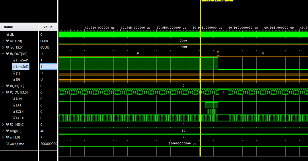
2. when and how do I send the VSync command? Currently I send it, during the last sub-period, before switching (see screenshot). Is this correct or do I need to have GCLK pause first? Do I need to be able to turn off the lines completely externally? (I can control with 2 bits the four lines, so one is always on...)

Thank you very much for your answer.
Kind regards,
MIchael Brandmaier

  • Hi Michael,

    1. It depends on the configuration you are using.  Please follow the calculation of  technical reference manual.

    2. You need to pause the GCLK before sending VSYNC. And after receiving VSYNC, the device will reset the GCLK counter, and the device will start to display again. And it doesn't matter which line is choosing at this moment, since no channel turns on.

  • Hi Shawn,

    thanks for your reply :)

    I have changed my VHDL code to control the TLC6946 as you and the datasheet said. Unfortunately i still have a problem:

    The display flickers briefly while switching from bank A to bank B and I don't know how to fix this problem.

    The FC registers look as follows:

    FC1 (Bit 15 - 0): 0110 0110 0000 1000   -> default values

    FC2 (Bit 15 - 0): 0100 0000 0000 0001   -> default values

    FC3 (bit 15 - 0): 0110 1100 0001 1010   -> dafult BC, SCAN_Line = 3 (4 multiplexing rows)

    FC4: default values

    Based on the settings in the registers, I calculated the number of GCLK using the formula on page 36 as follows:
    Number of GCLK = 2^n + LGSC1 + MGSE2 + 1 = 2^8 + 34 + 19 + 1 = 310 GCLKs.
    During these 310 GCLKs one multiplex line is displayed at a time, then the external Mos-FETs are switched over. If the whole was repeated 256 times for all 4 lines, the VSync can be sent (if new data was written into the TLC6946) -- if not, repeat GCLK and Line-Sel output.
    Because of these settings, I can't find my error and don't understand why my display flickers when switching.

    I hope this describes my problem understandably

    Best regards,

    Michael

  • Hi Michael,

    What kind of flicker did you meet, I wonder if the picture that displayed is right. If it is right, that means the data sending sequence and display sequence is right.

    you may need to check if the line switch time is enough(~1.5us), and whether GCLK is stopped when sending VSYNC

    Shawn

  • Hi Shawn,

    flicker is perhaps too strong a word.
    Lines that are not supposed to be lit always light up faintly. The content of these is that of other lines of the same driver.
    In the picture you can see this for example in the upper left corner. In line 1, 5 LEDs should light up, these also light up dimly in line 4. And I don't know where this comes from.
    Can you help me further on this?

    In addition: 1 driver always drives 16 x 4 LEDs, so on my board there are two drivers next to each other and four below each other.

    Michael

  • It seems the upper side ghosting. I suggest you to connect a Zener diode/  1000ohm Resister on each line to GND. it will supply a discharge path for line.

  • I have done this but it does't remove the effect. Any further idea?

  • would you send us the schematic?

  • Hi Shawn,

    i've done a lot of things and none of this led to a good result.

    I've added Zener diodes like you said and i've added a additonal signal to switch off all lines completly during GLCK pause. But nothing give me the expected result.

    Du you have any idea, what i can do?

    Best regards,

    Michael

  • Hi everyone!

    i resolved my issue. De screenshot about the Function control register is attached.

    I have changed the PWM align mode to: All PWM trailing edges aligned at the end of each sub-period

    Thanks to all for help! :)