This thread has been locked.

If you have a related question, please click the "Ask a related question" button in the top right corner. The newly created question will be automatically linked to this question.

UCC28C43: used as controller in 100V to 600V boost circuit

Part Number: UCC28C43

Hi,

my customer used this device to control 100V to 600V boost circuit.

The main power stage is as below:

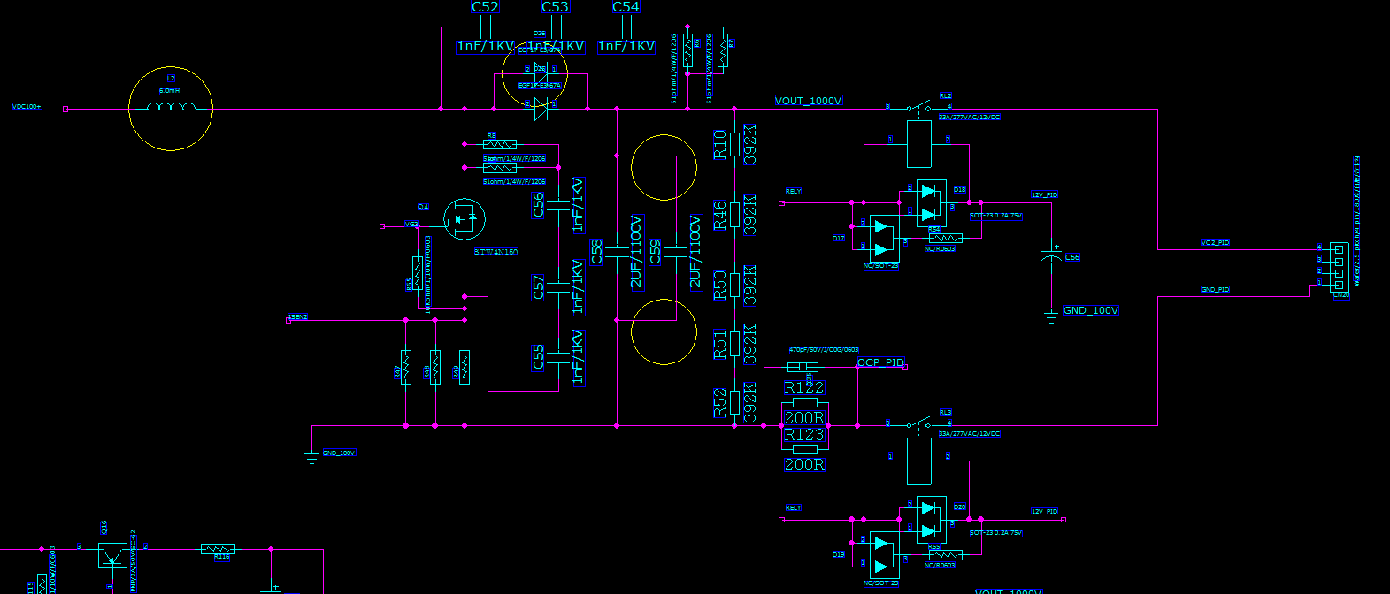
a dedicated 12V from AUX power to supply VDD of UCC28C43.

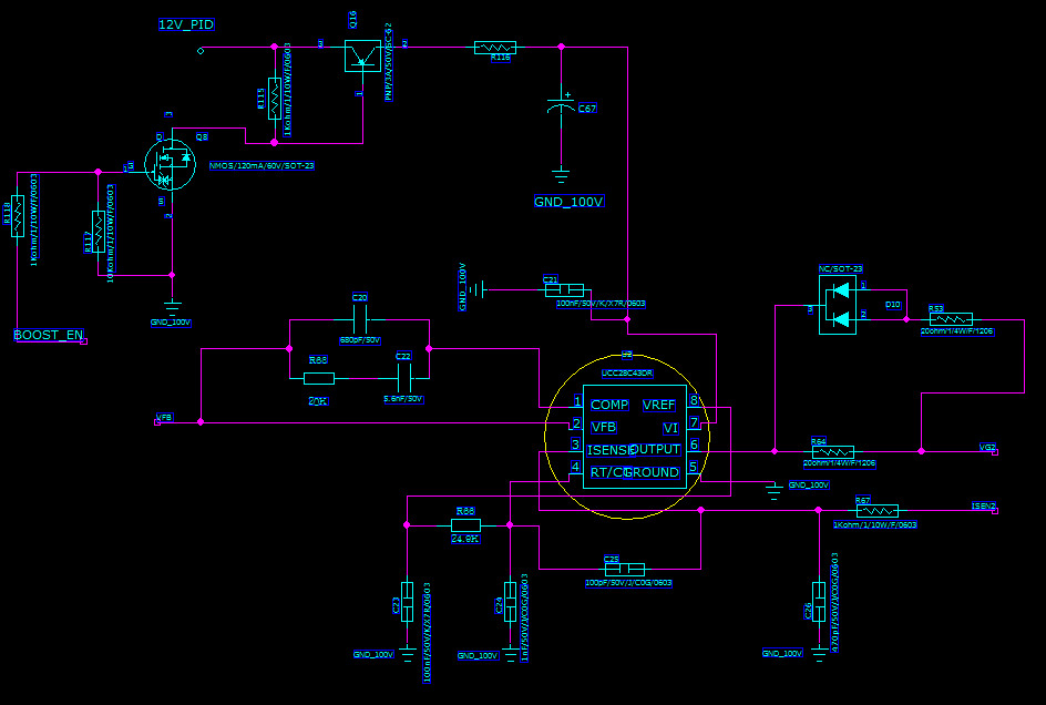
They find that the duty cycle is always around 98% and they don't know why. FB pin voltage is only 0.2V which is far away from 2.5V internal reference. They have connected resistor divider from output voltage to GND, Vfb=Vout*2.5k/600k. They expect UCC28C43 could adjust the output to be 600V and Vfb=2.5V.

Could you please help check if there is anything wrong in the schematic?

Do we have reference circuit for UCC28C43 to work in boost circuit?

If UCC28C43 is not suitable for 100V to 600V boost, are there any other recommended device?

  • Hi,

    If your FB stays at 0.2V, that means, your converter needs full duty cycle to make output voltage into regulation. You need check your feedback loop why FB stays at 0.2V. If your output voltage is low and not in regulation, then FB stays 0.2V is explained. If with duty cycle 0.98, your converter cannot reach Vout regulation, your converter design is not designed correctly. For example, if your boost inductance is too high or not. So you need to check review your design and measure your voltage and currents of output, MOSFETs, etc to debug.