This thread has been locked.

If you have a related question, please click the "Ask a related question" button in the top right corner. The newly created question will be automatically linked to this question.

UCC28950 open-loop operation?

Other Parts Discussed in Thread: UCC28950, UCC2895

We are developing a high-efficient dc-dc converter based on UCC28950 (Green Phase-Shifted Full-Bridge Controller With Synchronous Rectification). We are facing difficulties when trying to operate UCC28950 in open-loop configuration. We would like to set a fixed duty cycle without feedback for testing. Can anyone share information about how to operate this integrated circuit in open-loop configuration? Is it possible? Can we impose an external signal to pin 4 (comp) or is it going to damage the component?

  • One way to make the open loop test is first to disconnect all the circuitry connected to EA- and COMP, then connect EA- to COMP together, then add an adjustable voltage to EA- (or COMP as the both now connected). The duty cycle will be inversely to the EA- voltage and adjustable. (Both EA+ and EA- require connecting a resistor before connecting a voltage and please refer to the next reply I made).


    Another way is still to connect EA-and COMP together as in the first method, then disconnect all external circuit to EA+. Then applying an adjustable voltage to EA+. In this way, the error op-amp is connected in voltage follower, the duty cycle will be proportional to the EA+ voltage, and adjustable.


    Please follow either of the above methods to make open loop test. Directly imposing an external signal to COMP risks damaging the part. 

  • On the first method, the error op-amp is configured as a differential input amplifier. So both of its EA+ and EA- are required to have input resistors connected in between the voltage in that regarding and the each pin, EA+ and EA-.

  • do you have a diagram for the UCC28950 used in open loop mode?

  • Rene,

    I don't believe anyone has attempted to run it in that configuration. However, our customers are quite ingenious and someone may have done so.

    John

  • Ok, thank you very much, do you know another integrated circuit for phase shift control?, which can be used in open loop mode.

  • UCC2895 can do the job:

  • I believe that this was discussed on this form previously.

    If you want to run the UCC28950 open loop you should be able to do it by putting voltage amplifier in a voltage follower configuration.  Just tying EA - to OUT.  EA out should track EA +.  Suggestions for EA + is to put a voltage divider on and control is with a separate bias supply.  Starting with 0V and bringing it up slowly.

    I would also suggest that you get a hold of one of the 600W EVMs to evaluate.  You can order these from the ti web site.

    Regards,

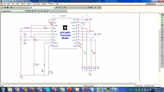
  • UCC28950 is not working in Orcad (open loop operation). However UCCx895 is working. I leave you the diagram.

    Best regards
    René