This thread has been locked.

If you have a related question, please click the "Ask a related question" button in the top right corner. The newly created question will be automatically linked to this question.

LM5155: CISS/ CRSS/ VDS, OFF

Part Number: LM5155

Hi,

The question is the same as the last question of the related thread.

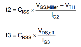
I heard that Rise/Fall time is calculated by the following equation according to the following document and the calculator uses the gate charges of the MOSFET as these a common values in the datasheet and the gate drive voltage of the MOSFET is know. .

https://www.ti.com/lit/ml/slua618a/slua618a.pdf

Could you tell me the actual values?

CISS:

CRSS

VDS, OFF

I would like to verify the calculation.

Best Regards,

Kuramochi

  • Hi Kuramochi,

    In design we usually refer to total gate charge Qg to estimate the switching transient, and T_on= Qg/Ig_source, and T_off= Qg/Ig_sink.   The referred article is a more sophisticated calculation, and I will have to forward your thread to the our FET group. 

    Thanks,

    Youhao 

  • Youhao-san,

    Thank you for your support.

    What my customer would like to know is how tr and tf are calculated on the above calculator.

    Best Regards,

    Kuramochi

  • Hi Tadahiko-san,

    Thanks for inquiry. I did not work on the calculator referenced in your earlier post. As you may have seen, there are many methods to estimate MOSFET switching times. At the link below, you will find an Excel-based non-synchronous boost FET power loss estimation tool. In the equations tab, there are detailed equations showing how the turn on and turn off times and associated switching losses are calculated. I believe this is similar but more detailed calculation. Please note, the switching times specified in the FET datasheet are very dependent on the driver circuit, PCB layout and MOSFET parameters including gate charge and internal gate resistance. Please refer to the blog in the second link below.