This thread has been locked.

If you have a related question, please click the "Ask a related question" button in the top right corner. The newly created question will be automatically linked to this question.

BQ76930: AFE fault/lockup and protection circuit draining battery overnight

Part Number: BQ76930
Other Parts Discussed in Thread: BQ78350

Seeking help as to what may have caused this as so far we are unable to replicate.

Have been testing a design using the BQ76930 & BQ78350 and it has failed such that the BQ76930 was running hot and discharged the battery overnight.

The pack had been charged and then discharged to ~30%.

Charger power output had been accidentally shorted the day before.

Pack was disconnected overnight and when going to reattach the device it felt warm.

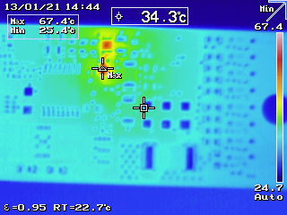
Top of board (BQ76930 U1 hot)

The heat source at the bottom left is the opposite side of Q5 / R73 shown below.

Bottom (REGSRC FET Q5B and resistor R73 hot.)

The 2.5V rail was not regulating. Battery had dropped to very low voltage before this was noticed.

No i2c comms with pack.

However disconnected the protection circuitry and powered it up with a test fix and everything is ok.

BBR and lifetime data didn't record anything of note.

Have connected the same board to another pack and abused it with a lot of shorts (100s so far) etc.

With no adverse effects seen. However have identified that VC0 / VC1 are dropping below Abs Max during

the short, the PACK is delivery ~100A during the short and the wires to Bat- / C0 are fairly long.

Will be fitting a schottky from GND to VC0 / VC1 to prevent this in the next revision.

All other points to the chips look to be in spec.

Any advice is appreciated as to what's going on.

Best Regards

Phil

094-DigiBat-Prot.pdf

  • Hi Phil,

    You don't mention the voltage of REGOUT other than it was not regulating.  From the thermal picture I suspect the REGOUT was shorted either internally or externally. The hot spot on U1 is likely the pin 1 end since the regulator is near that end.  If there were no hot traces on REGOUT it seems it would be internal.  Semiconductor devices can experience a condition called latchup, ICs are designed to avoid it and tested in qualification to be sure they are not sensitive to it.  I'm not aware of any sensitive of the BQ76930 to it.  There are occasional reports of cells drained without explanation.  The common trigger for latchup is high current from IC pins, so your observation of VC0, VC1 below VSS is a concern.  Customers have reported damaging ICs from such voltages.  It seems you have prepared for that with the TVSs on SRP, SRN and VC0. Having a negative on VC1 seems to indicate a large transient.  I don't recognize anything unusual in your schematic.

    From your description of results it sounds like it is an uncommon condition.  Adding the Schottky diodes you described seems a good plan.  Please let us know any further observation.  

  • The 2.5V rail was about ~1.6V while the AFE was locked up.

    The following scope capture shows the voltage at VC0 during a short.

    CH1 = VC0, CH2 = External Current , CH4 = C8 (on the PCB)

    And this shows VC1 during a short.

    CH1 = VC1, CH2 = C4, CH3 = C6, CH8 = C8

    I just noticed today that with the board that faulted the bottom 4 cells in the new pack that attached to the board now have a voltage ~ 90mV less than the top 4 cells. Confirmed with multi-meter and the AFE ADCs.

    This board was idle unconnected to anything for about 20hrs.

    Thermal camera doesn't show anything significant.

    Using a differential probe I measure voltage across

    R75 (1k filter to Bat+)

    Constant 50mV (50uA) with spike every 2 seconds to 200mV (200uA)

    R14 (1k filter to VC5x)

    Spike every 2 seconds to +/- 165uA

    R73 (100R resistor to REGSRC)

    250ms Pulsed 175mV (1.75mA)

    With occasional 40mV (400uA active periods)

    The 2s period and 250mS correspond nicely with the measurement periods.

    The other 1k filter resistors don't show anything untoward.

  • Hi Phil,

    As you said, the pictures show the VC0 is pulled below ABS MAX and limiting at conduction for most of the short circuit time.  VC1 is pulling down to conduct for part of the time.

    The measurements sound like the thermistor activations and communication from the BQ78350.

    It sounds like the cell offset voltage may have come from a prior event rather than your current measurements.  You might consider the part which got hot damaged. 

    Not sure what to suggest other than don't violate the abs max.