This thread has been locked.

If you have a related question, please click the "Ask a related question" button in the top right corner. The newly created question will be automatically linked to this question.

BQ76952: BQ76952: The IIC transaction to BQ76952 had not completed

Part Number: BQ76952

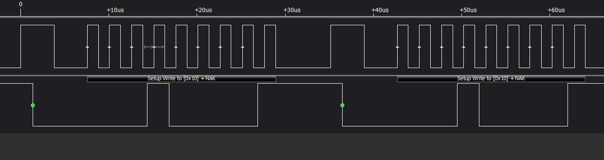
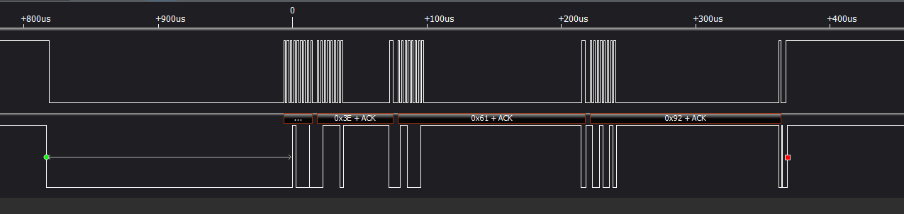
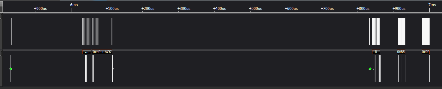
I have used the subcommand 0x0001 to try to read the Device Number. Communication protocol is IIC. But the device didn't answer my request.

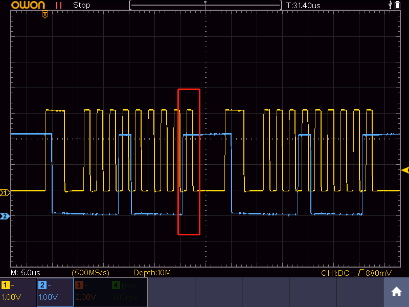
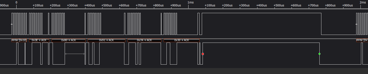
 The  oscillogramis shown in the figure above. Afer I send the 0x10 to device, it didn't answer the ACK signal to me.

I had measurement the REG18 pin, It had a 1.8V volte output. Is it means the chip is work normaly?

  • Hi Tan,

    The picture did not come through the post, it could be very helpful.  REG18 at 1.8V indicates that the part is awake and should be able to talk on I2C.  0x10 is the write address for the standard part, I would expect it to ack.

    Direct commands may be easier to start with than sub-commands, but most are read only.  Before the command can be sent though the part must ack its address.

    General recommendations are check the levels on I2C and the pull up, be sure the rising edges of the clock are clean.  Check that the I2C is reaching the IC.


  • Is there any BUG in the communication of this chip?

  • Hi Tan,

    Your waveform looks idealized.  Real signals never look that good. I see it is 400 kHz.  I would guess there are artifacts which may show in an oscilloscope waveform which may not be apparent here.  Check if the analyzer sees the same signal that the BQ76952 sees and if timing is met.  You might try slower clock to determine if there is a speed issue, but if it is due to edges it may not help.

    No communication bugs that I know.

    Direct commands are simpler and may be simpler to start. Direct commands will stretch the clock if needed.

    With subcommands which require data, see the protocol in the technical reference manual section 3.1 to check for the command echo before data is ready.  But the sub command would indicate the device has acknowledged its address.

    What operational mode is the part in with this communication?  DEEPSLEEP may need to start the internal oscillator and clock stretching may occur.

    There is some prior activity before time 0.  Is this a previous attempt to address the part?

  • this is the realy waveform,it's alse very good, but no ack.I have other questions:
    1.when I connect to battery, without Charger detection or TS2 pulldown detection ,but the REG18 is still 1.8V,does that mean the device is in normal mode
    2.I keep the RST_SHUT high more than 1s,but the REG18 is still 1.8V
    3.How can I shun down the device?

  • Hi Tan,

    It does look good.  Some thoughts:

    Are you the only user of the part/board?  Could the interface type have been changed to SPI or slow I2C?  I would try a slower clock.

    Is this an EVM or custom board?  If an EVM check the attachment location, it has a lot of jumpers.  For either type, be sure the signals get to the IC pins.

    You mentioned trying a subcommand.  Are direct commands working or do they look the same?

    1. With series FETs and the ESD capacitors across the FETs and PACK terminals the voltage applied to the Battery terminals divides about in half momentarily and wakes the part.  That is common.  The 1.8V indicates the part is on, usually in normal mode, it could also be waiting for power off.  If it is trying to go to shutdown but a pack voltage is held on the board (LD pin) or TS2 is held low the part won't complete shut down. See the description in the last paragraph of the technical reference manual section 7.5

    2. RST_SHUT high for >1s should shut down the part.  See the note above about soft shutdown.

    3. If you have no voltage on the pack (LD) and no pull down on TS and it won't shut down, the part is likely broken. 


  • Thank you for your answer, one of your fae told me there is a bug about I2C(earliest batch),I replace a new one then I2C is OK now.

    But I now find new problems:

    1.I use the subcommand 0x0001,and get the right answer 0x7952.I also can get the volt1,that mean I2C is ok and the device work normal.

      Then I use the same function to get 0x9261 ,but the answer is not right ,and the length in 0x61 is always 0x24.
    2.My ware have a long clock stretch, is there something?

    I also have some suggests:

    1.I found this chip is not so easy to use,direct cmd,subcmd,data memory .....,the current has cc1 cc2 cc3, the OTP have signature ...,many thing I am not very clear now

    2.I now have more than 7 doucument,

    3.Above all, every time I ask question with the afe,told me ask question here first,because  time difference I have to get the answer next day, this is low efficiency way.

  • When I read all 32 data buf,the cmd 0x9261 can get the right data(0x8c which i change),but the length is stll 0x24. I finally found the chip return all the value between  0x9261-0x92xx. So I can't get the actual length ?

  • Hi Tan,

    I learned there were some parts shipped which did not work.  Glad you have a replacement and it works.

    1. Glad the new part works.  If you read the full buffer the length is 0x24.  The technical reference manual section 3.1 describes the length as containing the command bytes, the response and data length.  "Therefore, if the entire 32-byte transfer buffer is used, the data length will be 0x24."

    2. The part does have clock stretching on some commands. 

    Thank you for the suggestions.  It is a very versatile part which makes it complicated.  The data sheet has key specifications and description.  The technical reference manual has key operational sequences and data.  Other documents are supplemental and may help explain some feature or use.

    See 1 above for the length.  With the 2 command bytes and 2 response bytes included, the 32 byte data shows a length of 0x24.  

  • 1.upper is my ware,downer is your ware in your doc, absolutely different

    2.read memory must have to read all 32data?

  • 1.I realize that read the data memory,the chip will fill all 32bytes buf?

    2.Now about current I have some questions:

      a.Is the cc2 the realy current caculate by the chip according to the CC Gain and Capacity Gain?

      b.I guess the cc2 formula is : CC2 = Vcur*CC Gain,Vcur is the volt measures between SRP and SRN

      c.If the Rsense is 5 mOhm,I need to set CC Gain to 1/2 = 0.5?

      d.How can I understand and use the Capacity Gain?

  • Hi Tan,

    1 Data memory read is like a subcommand that fills the buffer, yes.

    2a. cc2 is calculated with CCgain.

    2b. The part calculates cc2 current from counts using the CC GAIN value.  See the technical reference manual section 4.12.  It does not go voltage. 

    2c. CC Gain is calculated as shown in 4.12.  CC Gain = 7.4768 / (Rsense in mΩ)

    2d. Capacity Gain is used to determine passed charge capacity in userAmp-hours.  It is a constant multiplication of CC Gain:  Capacity Gain = CC Gain x 298261.6178 , see section 4.12 or 13.2.2.2

    This application note has a brief example of current calibration if it is helpful. https://www.ti.com/lit/pdf/sluaa32