This thread has been locked.
If you have a related question, please click the "Ask a related question" button in the top right corner. The newly created question will be automatically linked to this question.
Hello team,
we have a hand-held computerized spirometer that works with two AAA batteries or with USB.
We are using two schottky diodes in typical ORing configuration to provide power supply mux function (USB or batteries) and reverse polarity protection of batteries. Power supply from USB takes precende over batteries when device is connected to USB to save battery. Voltage from USB is 3.5V (LDO before ORing diode) and voltage from batteries is between 2V and 3V. The main disadvantage is the power losses in schottky when running from batteries.
We are considering replacing the schottky diode for the LM66100 because of its low price and of course its reduced power losses when running from battery.
The functionality remains the same:
- revere polarity protection from batteries only.
- USB power supply takes precedence over batteries.
- the intended use of spirometer is running with batteries assembled, but it's possible that somebody could use it from USB only without batteries.
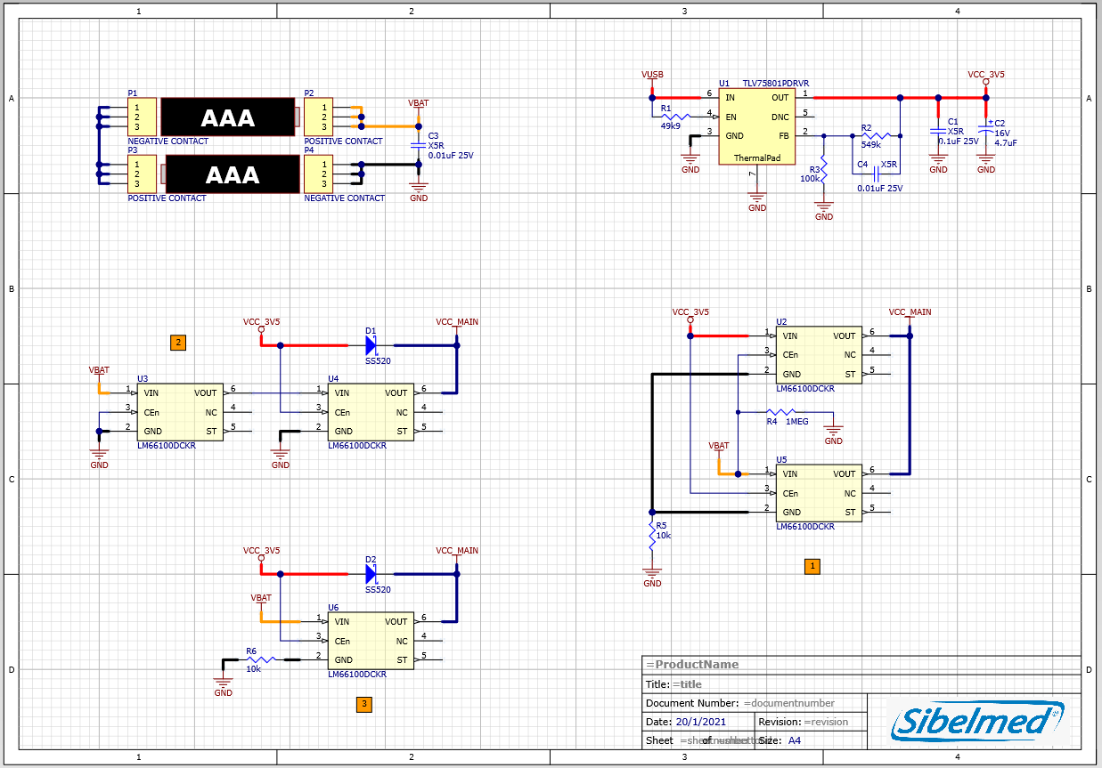
We are discussing three topologies:
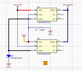
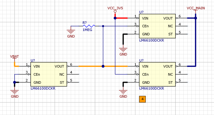
1) two LM66100 in ORing configuration with RPP by means of series resistor in GND pin to limit current
2) two LM66100 in series: first in RPP configuration and second in ORing configuration with a schottky diode in USB pwer supply path.
3) one LM66100 in ORing configuration with a Schottky diode in USB power path with RPP by means of series resistor in GND pin to limit during negative event
There are still some questions regarding these circuits.
- Is there any difference between RPP by means of serie resistor or RPP configuration (fig 12 of DS)? Is one circuit better than the other? I mean, in both cases load is protected from battery reverse polarity, so is it really necessary to add a dedicated LM66100 to RPP as in topology 2?
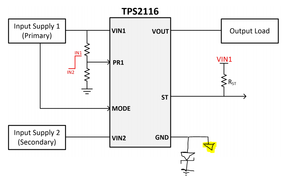
- In ORing configuration when batteries are assembled in reverse polarity the only possible path for current flow from battery is through GND pin to /CE pin, no currents flows through the load, right? Could we use a 10k series resistor to reduce current further during negative voltage event?
- What happens with /CE pin in ORing configuration if one of the power supply source is not present? In that case one of the /CE pins would be floating. I test with LM66100EVM in Vin1 and Vin2 and it always works but not sure if it's better to add a pull-down resistor (we don't want to add components if it's not really necesary due to space and cost constraints).
- In ORing configuration could we share one series resistor for both LM66100 GND pins instead of two series resitors, one for each LM66100, as in LM66100EVM?
Any advice on circuits proposed? What circuit do you think works better?
Best regards,
Ignasi
Ignasi,
The ORing functionality of LM66100 is not the same as power muxing. One drawback of LM66100 is that true RPP config cannot be used in a ORing configuration.
RPP as in Fig 12 of d/s would have the advantage over series resistor, but as stated, cannot be used in an ORING configuration. CE pin also does not conduct, and has no internal pulldown. As such , it cannot be left floating. Should have an external pulldown.
Based on your design goal, I would strongly recommend to use a Power mux, specifically TPS2116 instead of ideal diode(s). Power mux has several feature advantages over ideal diode for your application and can be configured for RPP protection.
Advantages include: Back to back diodes stop current in both directions, adjustable switchover voltage/prioritization point between your two inputs with 2 resistors (e.g. priority for your USB power according to your design goal), etc. This would also have a smaller PCB footprint compared with an LM66100 solution.
TPS2116 (and other PMUX) can be configured for RPP as in the figure below, a resistor parallel to the diode is optional.
Please let me know if you have any further questions on this topic.
Best
Dimitri
Hi Dimitri, thanks for the quick answer.
Yeah, TPS2116 it's a good option in performance, cost and size but unfortunately is in preview status, so I discarded before. I keep it for future designs but not for now.
I also discarded other muxes like TPS2115A, TPS2113A and TPS2121 because of its cost.
We have cost target of 0.6€ x1ku including assembly, so we need a low cost device but also with minimum external components.
The advantage of RPP over series resistor, I think, is that no current flows when battery is reversed, right?
Regarding circuits proposed (1, 2, 3) what do you think?
All circuits have the pull-down resistor on /CE pin (one dedicated and the other through the feedback LDO resistors)
What about circuit 2? First LM66100 provides true RPP while second LM66100 provides ORing function. The disadvantage is that we are doubling cost and forward voltage drop but they're still very low.
By the way, the advantage of the true RPP over series resistor is that in first case no current flows from batteries when they're reversed, right? In second case some current flows through GND pin. Any more advantages?
Could we implement RPP using a series diode instead of resistor in GND pin as you suggested in TPS2116 circuit?
Best regards,
Ignasi
Ignasi,
Ignasi Garcia Vazquez said:The advantage of RPP over series resistor, I think, is that no current flows when battery is reversed, right?
Yes s, as the diode breaks the circuit and the reversed supply "floats".
Another poster recently asked me the same question. A diode is very effective and cheap, but introduced losses no matter where you put it. A better solution is to implement the blocking function with a mosfet which reduces series losses and is still cost sensitive like a diode.
I recommend to use Circuit 1, with PMOS configured as below figure on the VBAT Line. This blocks the reverse current, protects against reverse polarity and has low series losses and cost. The similar thing can be done on the ground with an NMOS, as shown in our app note on the topic., but it leads to a very small offset from mosfet VDS.
And connect VBAT to CE of other LM66100 AFTER the PMOS. WIth this, series resistor/diode does not need to be used. but you should have the CE pin pulldown to prevent the pin from floating in reverse battery case.
Hi Dimitri,
thanks again! Clear, now, better a true RPP circuit thant series diode/resistors. But taking discussion a little bit further, what about replacing P-MOSFET with LM66100 in RPP topology? In fact, LM66100 it's a P-MOSFET with driver, RPP and some logic.
Comparing CDS23280F3 (lowest cost P-MOSFET from TI) with LM66100 I've found similar characteristics:
- Rds,on: 105 mOhms (measured @ Vin=2.5V, I=0.15A) vs. 130mOhms (DS Vgs=-2.5V, I=0.4A)
- Imax: 1.5A vs 1.8A
Main difference is the leakage current when off:
- Ioff: 5.1uA max vs. 50nA (better P-MOSFET).
P-MOSFET is also better in price and area:
- 0.036€ vs 0.058€ for 1ku
- 0.047mm2 vs 5.16mm2
But from manufacturing side, it's better use less references. I've done some calculations wit our usual manufacturing volumes and 3x LM66100 are cheaper than 2x LM66100 and 1x CDS23280F3.
From engineering side we don't see any limitation in replacing P-MOSFET with LM66100. We provide true RPP with first LM66100 and also reverse current bloking with last two LM66100 in ORing topology. What do you think? Do you know any downside we haven't seen? Do you think is better using P-MOSFET instead of LM66100?
So, now, we're considering replacing all two schottky diodes that we mount now for 3 LM66100 (one in RPP topology and 2 in ORing topology). We're reducing power losses but also cost and area.
Ignasi
Ignasi,
Ignasi Garcia Vazquez said:So, now, we're considering replacing all two schottky diodes that we mount now for 3 LM66100 (one in RPP topology and 2 in ORing topology). We're reducing power losses but also cost and area.
Ignasi Garcia Vazquez said:
This should be fine, i dont find any drawbacks of this solution, nor forsee any technical obstacles. The "extra" lm66100 is truly setup to emulate a real diode, so if we pretend it is a diode then the topology is very similar to what you proposed with the Schottky/PMOS solutions but with power advantage and cost advatange as you stated.
Also, thank you for sharing the insight about the manufacturing costs still being cheaper by reducing the BOM count by just that one discrete fet, using only LM66100, that is good to know! Its easy to forgot how low-price the LM66100 is.
If the PCB area increase by using this solution is OK for you, then i think what you have proposed is a good solution for ORing+RPP.
Best,
Dimitri