A related question is a question created from another question. When the related question is created, it will be automatically linked to the original question.
If you have a related question, please click the "Ask a related question" button in the top right corner. The newly created question will be automatically linked to this question.
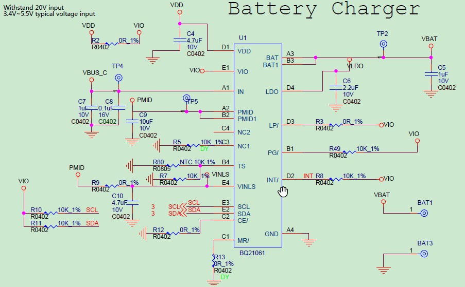
For the schematic, there are a few questions/statement just to ensure they match what you intend.
/MR pin pulled low. By default the BQ21061 uses this as a hardware reset button. Do you intend to change this? Pulling the /MR pin low may create issues when configured as a reset button by default.
/LP pin pulled to VIO. The /LP pin allows for the configuration of low power mode when powered by the battery. By pulling this high, the device will not operate in low power mode when only powered by the battery
Thanks for the reply. Actually, I will use a MCU(3.3V ) to control BQ21061 in this design, Please kindly further suggest how to connect below four pins to MCU.
The /LP pin is an input pin for the BQ21061, it does not need a pull up if your MCU is going to be controlling the /LP pin. The /INTand /PG pins do require a pull-up, as they are open-drain status indicator outputs.
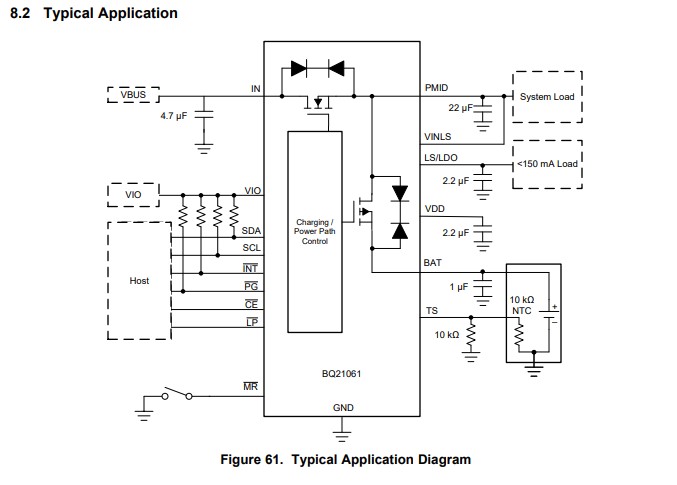
The /MR pin is intended to used with a push-button for a manual user reset. You can look at the typical application design in the datasheet that I've attached.