This thread has been locked.

If you have a related question, please click the "Ask a related question" button in the top right corner. The newly created question will be automatically linked to this question.

UCC29002: UCC29002 Excel Calculator Tool in A Low Side Current Sense with V+ sensing only (No R_SENSE)

Part Number: UCC29002
Other Parts Discussed in Thread: UCC28951, PMP20657, UCC27714EVM-551, PMP8740, PMP10099

Hello,


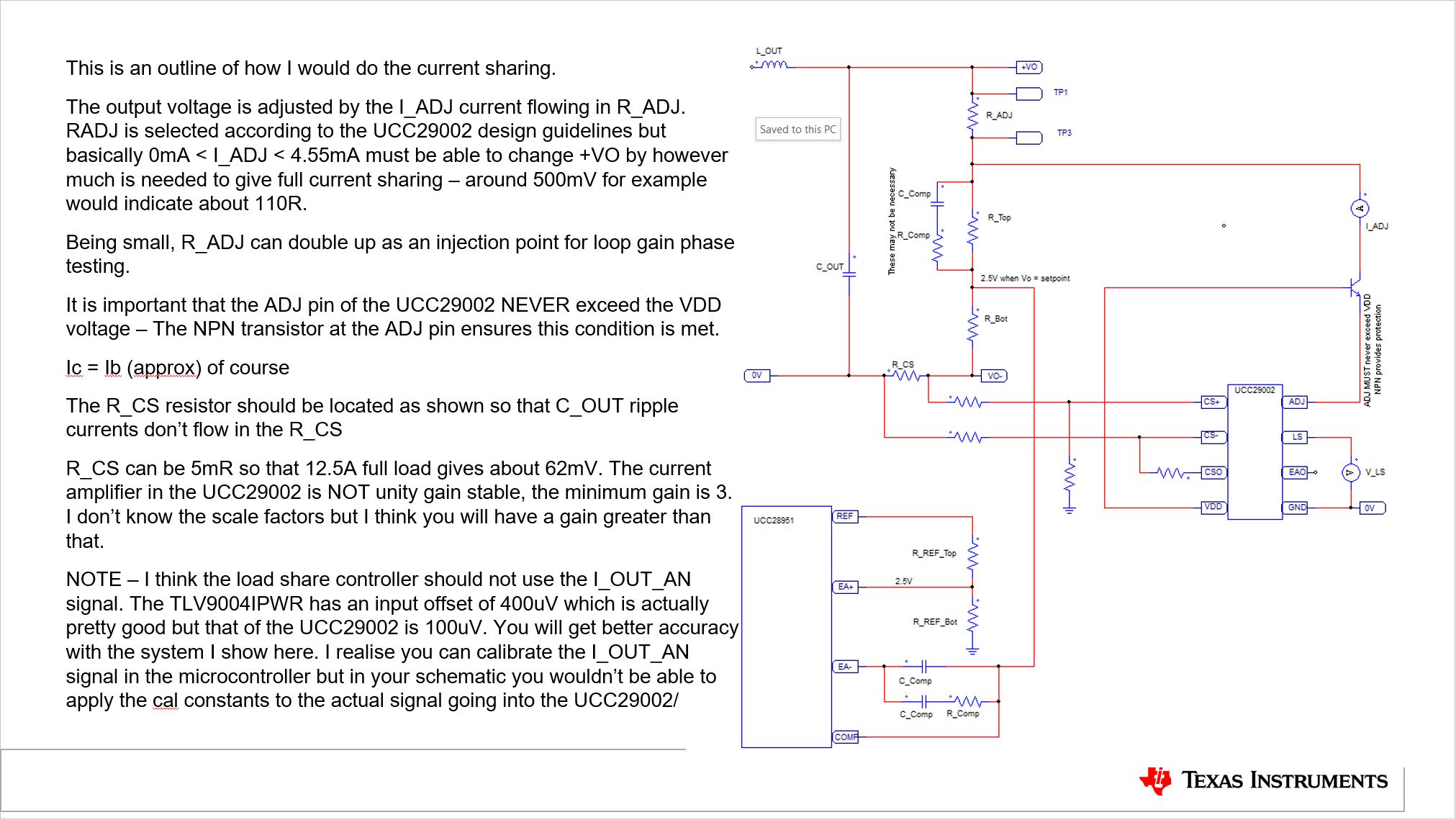
I am trying to use UCC29002 as a current sharing controller with 600W/48V PSFB Power Supply Module based on UCC28951. The current sensor is on the low side of the output as shown in attached schematic.


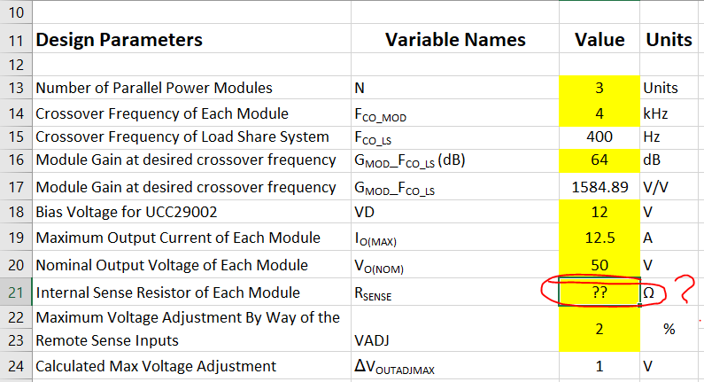
I am trying to use UCC29002 Excel Calculator Tool for A Low Side Current Sense with V+ sensing only. The issue is that I couldn't find any reference on what value should be used in the "Internal Sense Resistor of Each Module: RSENSE" field. Not sure if there are different equations to calculate Radj and the compensation network components. I though that RSENSE is equal to Radj in this configuration but that doesn't seem right as the resulted values didn't make any sense (i.e., Radjust (min)2 is either very large (900 ohm) or negative, CEAO is > 200UF). Please check out the attached Excel Calculator values and help to compute the values!3034.UCC29002_Calc.xlsx

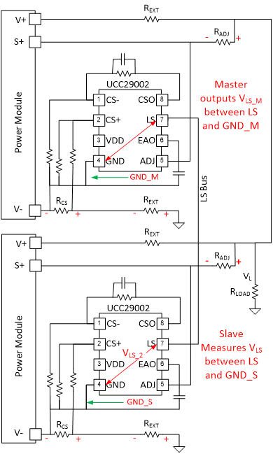
Colin Gillmor put together a great presentation file on "Load Share Control using the UCC29002". Slide 23 illustrates how to connect UCC29002 in A Low Side Current Sense with V+ sensing only. But there is no info about how the calculations should change. I also ran this design by him last year and he confirmed the circuit.


Your prompt detailed feedback is highly appreciated.

BR,

e RSENSE
  • Hi WB,

    please allow me more time on this post and I am planning to reply to you next Monday.

    Sorry about the delay

  • Hi WB,

    putting current sense resistor at low side or high side can use the same calculator since there is no difference between those.

    Rsense is a inner impedance from the modules that need to be used for current share.

    From the Mathcad tool of UCC29002,  the Rsense resistor should be measured between Vout+ and Sense+ during the development of the module.

  • Hi David,

    Radj is between Vout+ and Sense+, nothing else. If you measure the resistance you will read Radj. Sense+ is the feedback signal to the compensation network on UCC28951. If I plug Radj as Rsense in the Excel sheet, I get nonrealistic values for Radjust (min)2 and CEAO. Please try that with the Excel sheet attached to my first message.

    Let's make sure we are on the same page and use a reference design such as UCC27714EVM-551, PMP8740, or PMP20657. What would Rsense be if we use the same load sharing configuration in this case? 

    Thanks

  • Hi WB,

    I try to use the excel calculator attached but because there is no formula showed on the calculator, so the Radjust(min)2 will be negative if you put a resistor Rsense between V+ and S+ with a very small value, like 10ohm.

    I suggest you can use the Mathcad tool of UCC29002, and in the calculator, Radjust min)1 for avoid BJT from saturating. Radjust(min)2 to limit the Iadj not higher than 7mA limitation.

    the Mathcad version is in the attached. all your system's parameter is already filled in this calculator.

    for the Rsense location, you can refer to PMP10099, also it is in the Colin's presentation page 37.

    I suggest you can put Rsense=500ohm or higher, then Radj at 200ohm.

    https://e2e.ti.com/cfs-file/__key/communityserver-discussions-components-files/196/1111loadshare_5F00_worksheet_5F00_web_5F00_UCC29002.7z

  • David,

    The reference you provided (PMP10099) uses UCC29002 in high-side current sensing, where RSENSE (R16_B) is located on the left side of RSHUNT (R3_B) and RADJ (R11_B) is located on the right side of RSHUNT. My design implements LOW-SIDE CURRENT SENSING with V+ ONLY for a reason. If you move RSHUNT (R3_B) in PMP10099 to the low side, you can't keep RSENSE (R16_B) as it will become in parallel with RADJ (R11_B). 

    1) Please consult with the UCC29002 design team for a valid solution and let me know if UCC29002 will function properly in low-side current sensing with V+ only.

    2) Also please ask if I could use CSO output from the UCC29002 for measuring the current instead of using another INA chip. Indeed, CSO should be properly buffered. 

    I have attached the slid Colin sent to me regarding this design before he just left TI. I couldn't find any design reference except Colin's presentation and the design he provided.

    I need to make a conclusive decision whether to adapt UCC29002 in my final design revision or move away from this solution. 

    Thank you

    WB 

  • Hi WB,

    the slide in your previous post from Colin shows that Rsense we are talking about is gigantic.

    if you open the Mathcad file I added, you can find that if you change the Rsense to gigantic, it only influence a little on the Radj resistor.

    PMP10099 in parallel Radj and Rsense through the current sense resistor, because the current sense resistor is much smaller than Rsense, so it can be ignored here. So I suppose it is the same as the current resistor placed on the negative side of the output bus.

    actually a lot of customer use low side current sense resistor when using this load share controller. please double confirm on the real project or you can use a EVM to do the evaluation.

    CSO surely can be used as a current sampling signal if the signal is high enough for you.

  • Hi David,

    Thanks for your feedback. 

    1. Assuming Rsense = 200K, Radj is calculated as 157 OHM. I used 220 OHM for Radj, 22uF for C_EAO, and 100 OHM for R_EAD. The system seemed to share the current with very good accuracy between two paralleled modules. I still need to test with more than two modules in parallel later.
    2. Colin recommended to connect the LS signal to the bus with a 1K series resistor. I had to short the resistor to get the system to work. Otherwise, it will not work at all. 
    3. Do you see a value of using D1 in series with Q2? 
    4. What is the expected accuracy at CSO output? Any recommendation about proper buffering between the CSO output and 3.3V ADC?

    Thank you!

  • Hi, WB

    Wenbin is out of office, let me continue to support this thread.

    It seems the item 3 and 4 should be answered:

    Regarding item 3, it does need D1 and Q2, since there is transistor on ADJ pin internal.

    Regarding to item 4, the input offset of OPA of CSO is 100uV, the accuracy is related to gain from CS+- to CSO. For example, the gain from CS+- to CSO is 50, and output full range is 10V, the output variation is 50*100uV/10V

    Yunsheng

  • Hi WB,

    do you still have any question on this post? if no, please allow me to close the post.

    Wenbin

  • Just 3 points I would make sure about:

    - D1 is not considered in the datasheet and I am still wondering if it's needed.

    - Do you have any reference on using CSO for reading the current?

    Please close the post right after your feedback.

    Thank you 

  • Hi WB,

    I did not see other customer use the D1 diode here. There is no need for this diode.

    unfortunately all the reference design consider this controller as the load share controller, so there is no a reference design use CSO as current sampling.

    if you still warry about cso as current sampling, I would suggest adding an emitter follower.