This thread has been locked.

If you have a related question, please click the "Ask a related question" button in the top right corner. The newly created question will be automatically linked to this question.

TPS2595: we are studying the possibly of limit the power at secondary 12V side by TPS259541DSG or TPS259571DSG

Part Number: TPS2595

Hi TI Team,

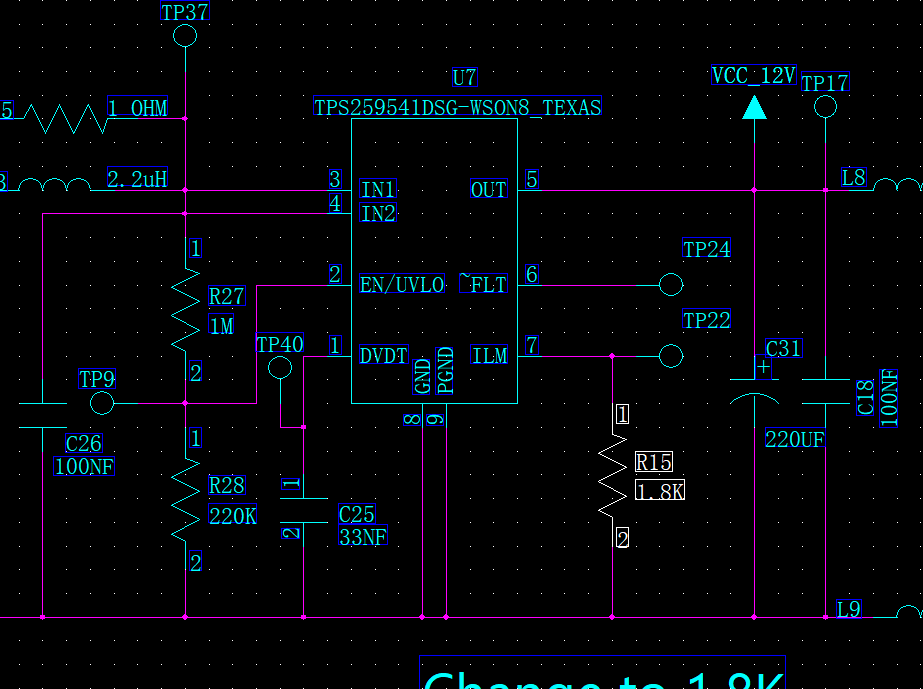
We are now modifying our circuit based on TPS259541DSG. But I have below questions when using it, can you help to answer?

A quick response will be much appreciate, we are quite in hurry.

1.            Can fault pin left float?

2.            Can inrush current trigger over-current protection?

3.            How to deal with large capacitance when start-up? Should I use the maximum dVdt to reduce the time at current limit state or use a lower ramp rate?

4.            How to handle the back emf from relay at steady state?(The customer's load is working with 6 relay switches.)


I’m using the TI calculation tool, but it turn out give some errors on my input. Our load is a large capacitor and 2 DCDC convertor

Parameter

Description

Value

 Units

Tolerance

3.3V or 5V or 12V version

Refer Table-1 and select based on OverVoltage Clamp/Cut-off and Active High/Low requirement

TPS259541


VIN (max)

Maximum Operating input voltage (magnitude)

13.20

V


UVset

Undervoltage Threshold (VIN Rising)

7.00

V


VUVP

Internal Undervoltage Protection Threshold (VIN Rising)

2.54

V

3.7%

Cout

Load Capacitance

300.0

uF

10.0%

Rlstart

Load at start-up (assumed to be resistive), Refer to Section 9.2.2.3.2 in Datasheet

150.0

Ohm


Imax

Maximum continuous load current (magnitude)

1.1

A


Ilimit

Current Limit, 7.5% higher than maximum continuous load current

1.18

A


VOVC

Over Voltage Clamp

13.70

V

4.5%

Please also help to comment our circuit design.

  • Hi Ken,

    Welcome to e2e. Please see:

      1.   Can fault pin left float?

    Yes if you are not using it you can leave it open.

    2.   Can inrush current trigger over-current protection?

    Yes. During startup if total inrush current becomes greater than current limit then the device will have a current limit startup . Please see datasheet section 9.2.2.3.2 Case 2: Start-Up With Load. Output Capacitance COUT and Load Draw Current

    3.            How to deal with large capacitance when start-up? Should I use the maximum dVdt to reduce the time at current limit state or use a lower ramp rate?

    To deal with large capacitance , you can increase Cdvdt cap . With increase in Cdvdt cap ,output voltage ramp rate decreases due to which inrush current decreases.  

    4.            How to handle the back emf from relay at steady state?(The customer's load is working with 6 relay switches.)

     To deal with transient due to inductive load please use cap and tvs diode at input and shottky diode at output. 

    Can you send the filled design calculator ? It is needed for schematic review.

    Regards

    Kunal Goel 

  • Hi Kunal,

    Thanks for your response.

    I have trouble on filling design calculator. For parameter Rlstart, as our load is not linear, I have no idea how to define the R.

    The load is 2 DCDC switching converter which further convert the 12V output from eFuse to 5V and 3.3 for other system, should I just use its sourcing current and assume it as resistive?

    Anyway, this is the filled calculator, please comment.

    I add a BAT54WS on the output and adjusted the CdVdT_ext to 22nF as the calculator suggest

    PS. Due the the board system limitation, I save as the file as xlsx from xlsm.

    TPS2595xx_Design_Calculator_RevA_review.xlsx

    Regards,

    Edmond

  • Hi Edmond,

    The reason for cout and rlstart field becoming purple was that device startup current was greater than Ilimit so device will have a current limit startup.

    The schematic looks fine. I will get back to you regarding the estimation of load during startup. Can you send some more parts of schematic to know the exact output load? You can also share the information on mail with me .

    Regards

    Kunal Goel


  • Good morning Kunal,

    I solved the purple by relaxing the ramp up rate and put capacitance closer to my circuit which is less than the one at #1.

    Please check my attachment at #3.

    What is your email?

    Regards,

    Edmond

  • Hi Edmond,

    Sent you the friend request .

    Regards

    Kunal Goel