This thread has been locked.

If you have a related question, please click the "Ask a related question" button in the top right corner. The newly created question will be automatically linked to this question.

ULN2004A: Pulse Current Rating on collector

Part Number: ULN2004A

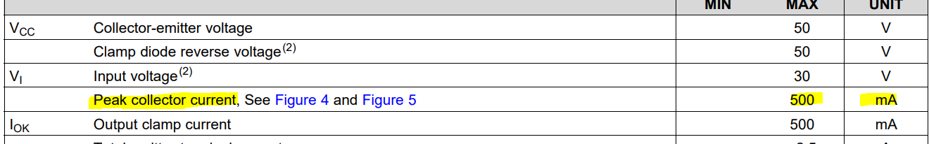
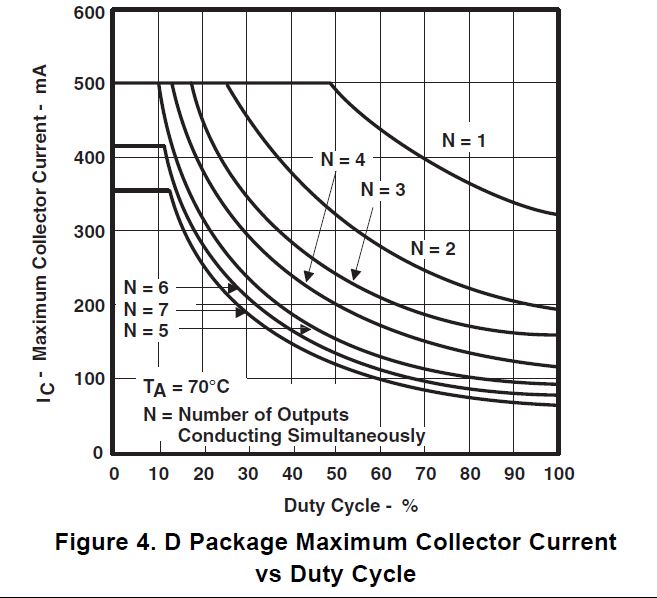
I am looking for the pulse current rating for the collector outputs. The data sheet has Figure 4 which shows the Maximum collector current based on outputs conducting and duty cycle %. However, I do not see anywhere that states what the frequency is for the duty cycle. I am trying to find how much current the collectors can take for a 20us to 200us pulse ranges.

  • Zach, 

    The peak collector current rating, even for pulses is 500mA even for short pulse.If you need higher currents, you can parallel multiple channels together. 

    Please let me know if any additional questions. 

    Best

    DImitri

  • Can you please explain more Figure 4 in the datasheet. What is the frequency used to make the graph. I'm trying to understand what the time frame used to produce the graph. For example, what is the 50% duty cycle time reference? 0.5 secs on and 0.5 secs off? 0.5ms on and 0.5 ms secs off? 0.5us on and 0.5 secs off? ect...

  • Zach Bruce said:

    Can you please explain more Figure 4 in the datasheet. What is the frequency used to make the graph. I'm trying to understand what the time frame used to produce the graph. For example, what is the 50% duty cycle time reference? 0.5 secs on and 0.5 secs off? 0.5ms on and 0.5 ms secs off? 0.5us on and 0.5 secs off? ect...

    The Figure 4 is independent of frequency and you dont need it to find out how many simultaneous channels you can run. 

    When you have a high duty cycle, the darlingtons are sinking current and dissipating heat, so the more channels you have, the more heat. The higher duty cyel theyre on, the more heat. Theres a limit to the heat, thermal resistance is different for N/D packages which is why Figure 4/5 are slightly different. 

    note that figure 4/5 is at 70C ambient, and also the PEAK (the entire area below each curve is valid operating region for N=x # channels. If your ambient temperature is hotter and/or youre going to be running some channels at a certain duty cycle and others at a different duty cycle, you can apply the way the Figure 4 is generated by finding the max power you can sustain in Section 9.2.2.3, of the datasheet, excerpt below. 

    I have added the "xD_i", which would be the duty cycle for the channel i..

    Please let me know if you have any further questions, if this answers all your questions please press the green button. 

    Best

    Dimitri