A related question is a question created from another question. When the related question is created, it will be automatically linked to the original question.
If you have a related question, please click the "Ask a related question" button in the top right corner. The newly created question will be automatically linked to this question.
Connection problem about "PWRHOLD" pin of TPS65910 for AM3517 ?
PWRHOLD connected to VRTC, and when power on TPS65910, it enter in active state immediately.
choice 2:
PWRHOLD connected to VIO/VDD1, and when power on TPS65910, it should be wait user to press switch-on button ( PWRON is "low" in several milli-seconds). and TPS65910, it enter in active state.
You want to have a push-button on PWON pin, is that correct. This will allow you to power on the device by pressing the push-button. In this case it doesnt matter where PWRHOLD is connected.
You are right, "PWRHOLD " and "PWRON" are conditions for TPS65910 active state alternatively, (TPS65910 datasheet page.41)
How long does the "PWRON" signal drive to low level to active the TPS65910? If I use push-botton, is it OK? (Because user may press the button quickly), or I should choose SPDT switch alike?
I do have problem with this PWRHOLD connection and really hope you can help to confirm it: as my understanding PWRHOLD is used to maintain Power ON status after all of power rails are up, and it should also return to zero once power -off procedure is completed. According to this it is make sense to connect this pin to VIO, but I don't understand how it could work if it connected to VRTC because VRTC is a "ALWAYS-ON" rail as long as VBAT is applied. It means PWRHOLD will never go chance back to zero unless the battery is removed. How it could be used for power control if it is done this way?
I also have problem to turn off TPS65910 even I have PWRHOLD connected to VIO(directly), simply because VIO was not fully back to zero after shunt-down process(for some unknown reason) so that PWRHOLD remain at a certain of level (about 0.8V), it causes TPS65910 back to power on status again.
As you said, if PWRHOLD is connected to VRTC, PWRHOLD won’t go back to zero and consequently we cannot say that PWRHOLD is used for power control.
PWRHOLD pin is usually connected to an external signal for PMIC power up/down control. If we look at the "Device state control through PWRON" timing diagram (p32 of the TPS65910 datasheet), we can notice that there is a delay (called t_dONPWHOLD) to set high PWRHOLD signal or DEV_ON control bit after NRESPWRON is released to keep on the supply.
If you do not want to use this functionality, you can put PWRHOLD to a high level. To do it, the best way is to connect it to VRTC because it is part of its supply domain (see table exposing the terminal functions p38 of the TPS65910 datasheet).
t_dONPWHOLD - delay to set high PWRHOLD signal or DEV_ON control bit after NRESPWRON released to keep on the supplies.
What is the significance of the delay? if we make PWRHOLD signal high before that delay or before NRESPWRON goes to high, what will happen?
When we set DEV_OFF bit, PMIC will turn off. Is it necessary to make the PWRHOLD signal low to keep the device turn off?
If the above requirement is true to turn off the PMIC than how can PMIC_PWR_EN ( this signal will remain active till the RTC domain of AM335x is powered) signal of AM335x be used for PMIC PWRHOLD as implemented in AM335x EVM or it means AM335x EVM cannot be turn off by setting DEV_OFF.
t_dONPWHOLD allows the processor to acknowledge the power on sequence and complete it. Indeed, after receiving NRESPWRON, the processor can complete the power on sequence by setting PWRHOLD or the DEV_ON control bit to 1. The typical value of the delay is 984ms (see datasheet p33).
It is not necessary to make the PWRHOLD signal low to keep the device turn off. If DEV_OFF bit is set to 1, then the POWER ON will be disabled.
When we set the DEV_ON bit the device will turn off once but restart again as PWRHOLD is the enable condition of the device as per my understanding( pg-41).
Can we make PWRHOLD high before NRESPWRON goes high through some external device?
It depends on the application. As specified in the TPS65910x checklist (available on TI website) : PWRHOLD can be connected to an external signal for PMIC power up/power down control or if control is not required, then it can be tied to VRTC. PWRHOLD can be high before NRESPWRON goes high.
Kindly clarify this diagram according to your explanation in above post.
Let PWRHOLD is tied to VRTC and device is turned off by writing DEV_OFF to 1, Input power of PMIC is still present and as the PWRHOLD (connected to VRTC) is high, PMIC will start again.
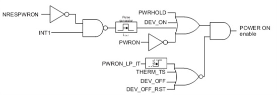
Please find below the explanations of the diagram used with the state machine:
Table1:
Turn on request (to launch power on sequence) :
If one of the events listed in the following table occurs AND MB>VMBCH, the power on sequence of the device is launched unless one of the gating conditions listed in Table 3 is present.
Event
Polarity
PWRHOLD (pin)
HIGH
PWRON (pin)
LOW
NRESPWRON=0 and INT1 gets ACTIVE (a new interrupt comes while in OFF)
TRUE
For interrupt sources that can be configured as ON requests, see Table 4
INT1 ACTIVE means :
INT1
DEVCTRL2_REG.IT_POL
0
0
1
1
Table 2:
Keep on conditions
If one of the conditions listed in the following table occurs before tdONPWHOLD delay, the device will be kept on unless one of the gating conditions listed in Table 3 is present.
Event
Comment
Polarity
PWRHOLD (pin)
must be set before tdONPWHOLD
HIGH
DEV_ON
must be set before tdONPWHOLD
1
PWRON= LOW AND DEVCTRL2.PWRON_LP_OFF=0 AND DEVCTRL2.PWRON_LP_RST = 0
must be true before tdONPWHOLD
TRUE
with t_dONPWHOLD delay to set high PWRHOLD signal or DEV_ON control bit to 1 after NRESPWRON released, to keep on the supplies (typical value: 984 ms )
Table 3:
Turn on and keep on gating conditions
If one of the conditions listed in the following table occurs, it will prevent any switch on sequence and will turn OFF the device if in ACTIVE state.
Event
Maskable
Polarity
PWRON_LP_IT
Yes, using INT_MSK_REG.PWRON_LP_IT_MSK This will mask the interrupt but not the switch off condition. To mask the switch off condition, need to disable the feature by setting DEVCTRL2.PWRON_LP_OFF=0 AND DEVCTRL2.PWRON_LP_RST = 0
1
THERM_TS
Can be disabled using Therm_REG.THERM_STATE
1
DEV_OFF (event)
No
1
DEV_OFF_RST (event)
No
1
MB <VMBLO
No. This condition makes the device go in BACKUP state
TRUE
Table 4:
Interrupts leading to Turn on request
Event
Maskable
Polarity
PWRON_IT
Yes, using INT_MSK_REG.PWRON_IT_MSK Switch on even if interrupt masked
HIGH
PWRHOLD_IT
Yes, using INT_MSK_REG.PWRHOLD_IT_MSK Switch on even if interrupt masked
I want to use TPS65910 rtc as a wake up source. What are the registers I have to configure with what values so that I can use it as a RTC wakeup source.
I configured INT1 pin as active low in dts file like this:
interrupt-parent = <&intc>;
interrupts = <3 21 IRQ_TYPE_LEVEL_LOW>;
And in rtc-tps65910.c driver, It is configured like this:
ret = devm_request_threaded_irq(&pdev->dev, irq, NULL,