This thread has been locked.

If you have a related question, please click the "Ask a related question" button in the top right corner. The newly created question will be automatically linked to this question.

LP87561-Q1: Impact of Cout_Local value on stability performance

Part Number: LP87561-Q1

Hi,

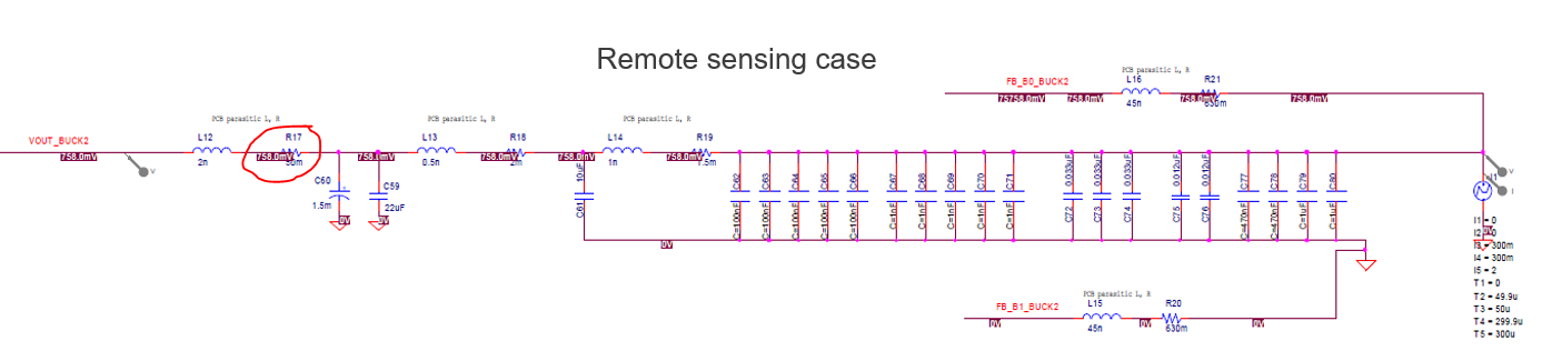
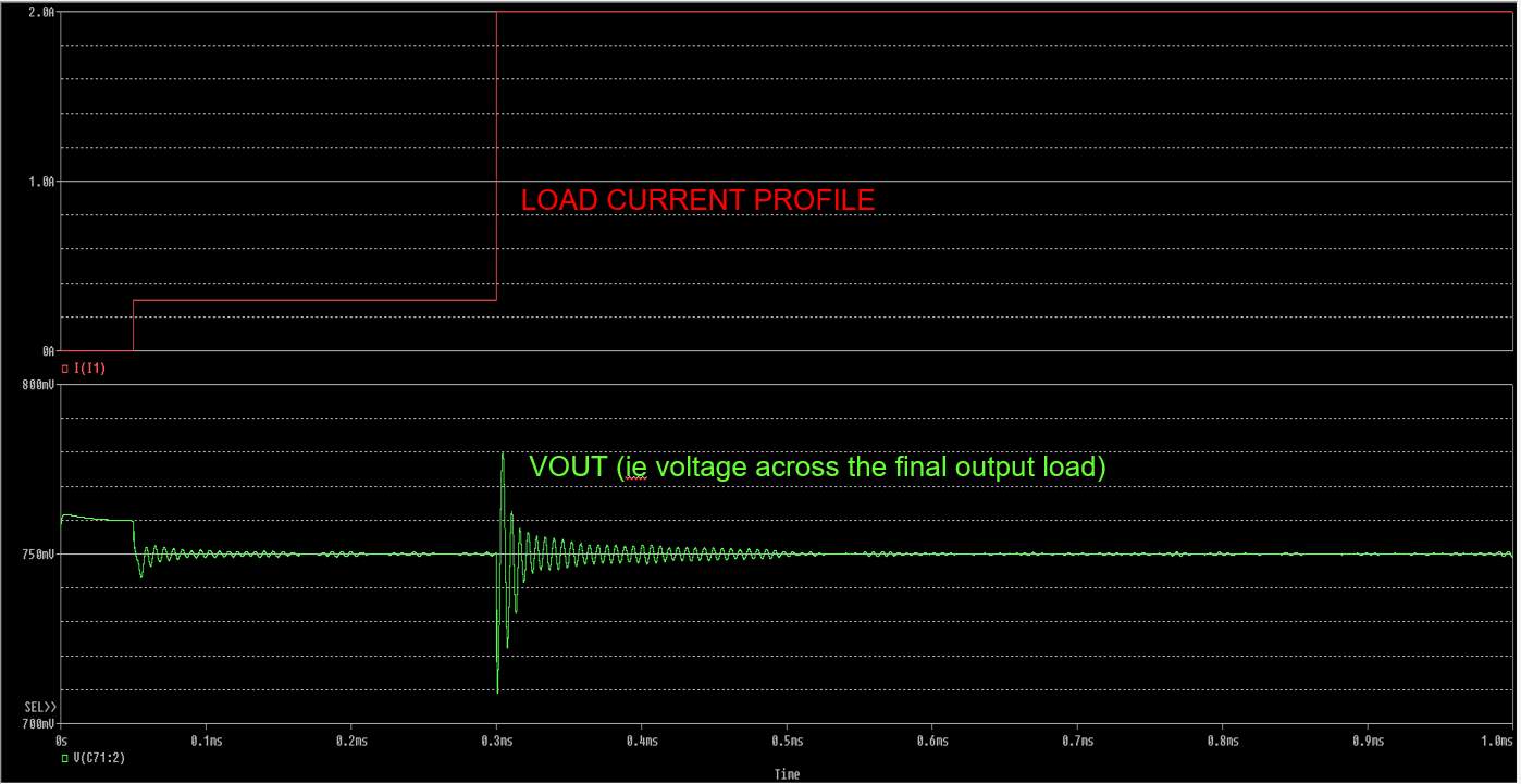
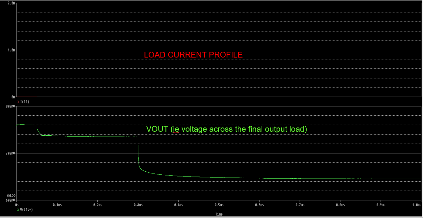
In the datasheet, the Output filtering capacitance per phase, ie Cout_Local is mentioned as 22uF typical. In the application report "Stability Considerations for LP8756x-Q1 and LP8752x-Q1" also, looks like Cout_Local used per phase is 22uF, although the C_PointOfLoad is varied as part of the analysis.

In general, the analysis result inside the app report suggested that increasing C_POL in general tended to improve the stability performance.

I was curious whether increasing the Cout_Local value used per phase beyond 22uF would also help gain some improvements on stability performance, or whether it is detrimental and hence not recommended. Can you please comment on the same?

Thanks,

Anoop

  • Hello,

    In general it is recommended to have bulk of the capacitance on one point and then smaller capacitance on the another point. It is ok to have the bulk of the capacitance right at the buck output and then have for example 22uF at the point of load. Impact for the phase margin would be the same as you would have 22uF at the buck output and then bulk capacitance at the point of load.

    Typical use case for these devices is processor power and they usually require quite a lot of capacitance close to the processor power pins. So in those cases it makes sense to have only 22uF at the buck output and them more at the point of load.

    Thanks.

    Regards,

    Tomi Koskela

  • Hi Tomi,

    Thanks for the details!

    Thanks,

    Anoop

  • Hi Tomi,

    If I may, can I pose one more question on this? Actually in my design the buck is going to be in a different board from the board that contains the load consuming the current from the buck. Both these boards will dock with each other using board to board connectors (www.digikey.in/.../2526700 and its mating part to be specific).


    The board with the load is pre-designed and I don't have control over the capacitances on that anymore. It essentially has a 1500uF bulk cap near to the docking connector, followed by a 10uF cap and a few smaller value decaps of 1uF, 0.1uF, 12nF etc (total some 3uF) placed close to the load.

    So you can see that there will be some parasitic inductance and resitance (say some 2nH and 10mohms) between the Cout_Local caps and Cout_POL caps. Even in this case, if I'm ok with not meeting the Output voltage slew-rate specifications, is it like I can add a significantly high value of Cout_Local (since I have no control over Cout_POL as I mentioned), say 91uF per phase in order to improve my phase margin? Say if I keep arbitrarily increasing the Cout_Local value, is the only issue with that that I will stop seeing significant improvments in phase margin beyond a point, or will too high a Cout_Local value start to negatively impact the phase margin and lead to instability?

    Thanks,
    Anoop

  • Hi Anoop,

    The best option is to have provision for extra capacitors and also add provision for taking phase margin measurements. Usually 50ohm resistor in FB_B0 is used to allow measurement signal injection to the feedback. In normal use 0ohm resistor would be used of course. 

    The output capacitor, parasitic inductance and then the POL capacitor form basically a pi-filter and it can have unexpected behavior on the stability of the converter. Actually the worst case is if the output cap and the POL cap are equal size. So having small buck output cap can be actually best for stability point of view, but without testing it is difficult to predict. SIMPLIS simulation can be used to estimate the AC performance if you have SIMPLIS license. SIMPLIS model is available from the product page.

    Thanks.

    Regards,

    Tomi Koskela

  • Hi Tomi,

    Yes, will include DNI options for extra caps if needed. Actually the 50mohm resistor I mentioned was the estimated parasitic resistance from the board to board docking connector contact resistance, as shown below:

    I did some simulations with the PSPICE circuit, since I don't have a SIMPLIS license. Is the accuracy of the PSPICE simulation circuit pretty decent and nearly comparable with the SIMPLIS model, or is it expected to be way off from an accuracy perspective?

    With remote sensing and with the parasitics mentioned, I seem to observe some ringing during load transient PSPICE simulations. With local sensing, I don't see ringing as such, but I do see the obviously expected IR drop from the series parasitic resistance. Attaching snapshots below (remote sensing case above, and local sensing below):

    Thanks,

    Anoop

  • Hello Anoop,

    With PSPICE you can only simulate the transient response, which can be ok for determining stability. With SIMPLIS you could run AC analysis as well, so you get actual bode plots with phase/gain margin. So it not really matter of accuracy, it is what kind of analysis you can run with SIMPLIS vs PSPICE.

    With local feedback it should be stable, it is with the remote feedback that you start seeing issues with the stability.

    Thanks.

    Regards,

    Tomi Koskela

  • Hi Tomi,

    Thanks a lot for the quick and detailed replies!

    Thanks,

    Anoop